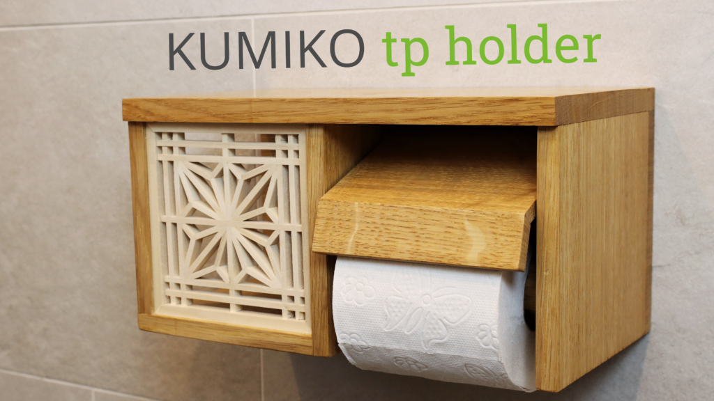
A dedicated storage solution for clamps in my shops was way overdue. I threw my clamps in the corner behind my workbench and always stumbled over them. I wanted to build a clamp rack that saves space, is close to my bench and can hold a variety of clamps.
Tools I used
- Track Saw*
- Festool Domino*
- Table Saw
- Band saw
- Router
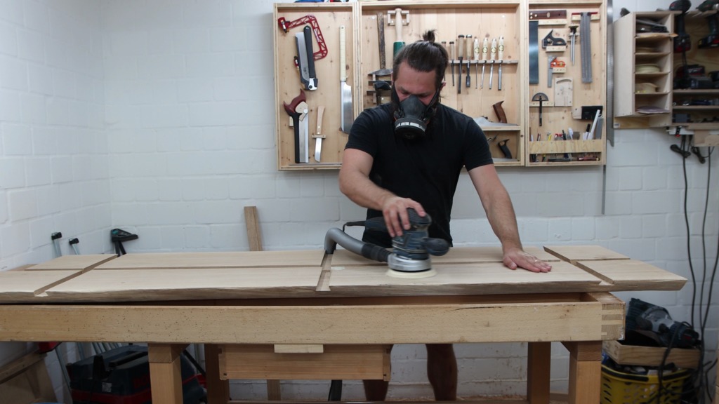
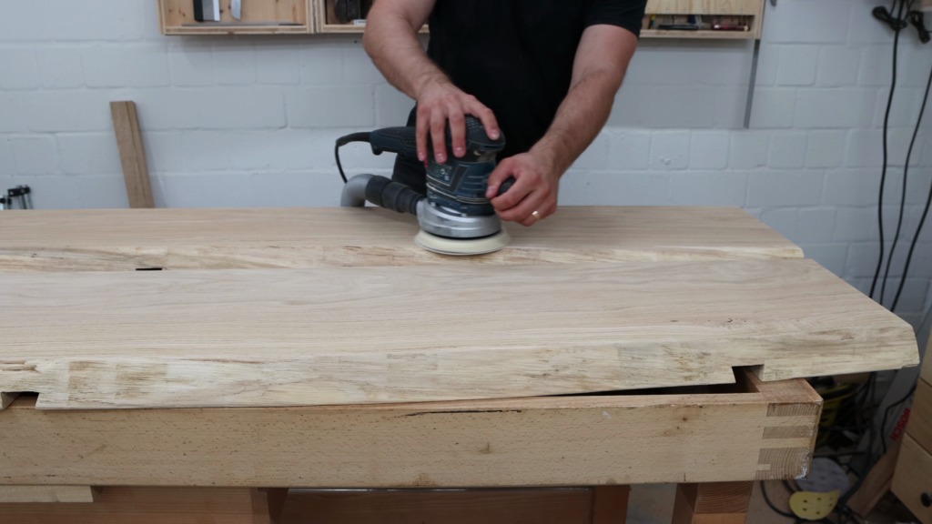
- Random orbital sander
Here you can find a complete list of my tools.
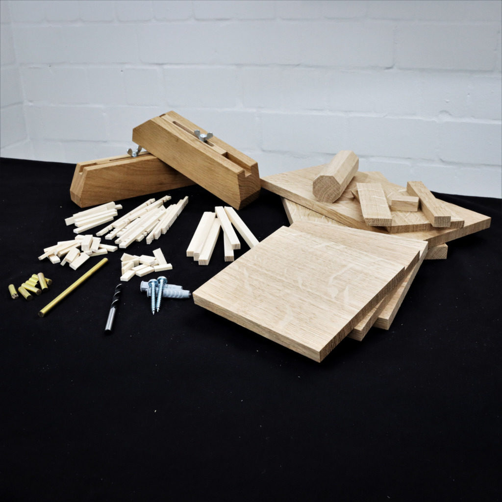
Materials and supplies
- 18mm (3/4″) birch plywood
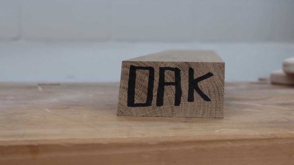
Clamps
Formatting the plywood
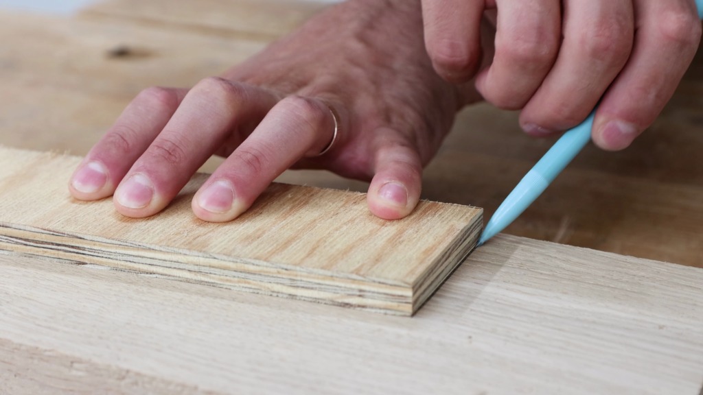
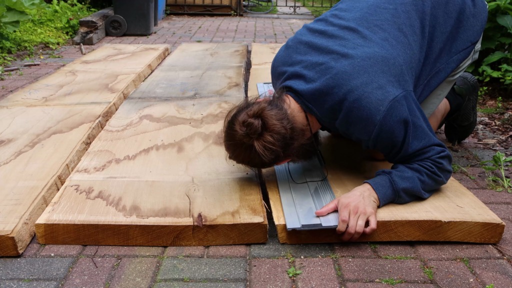
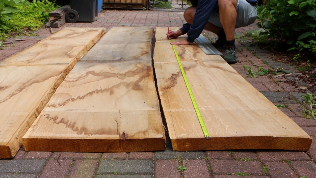
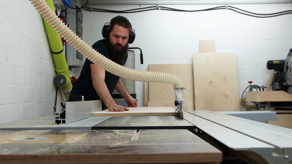
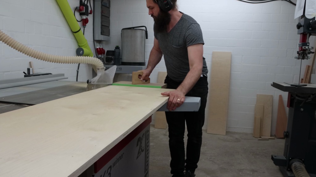
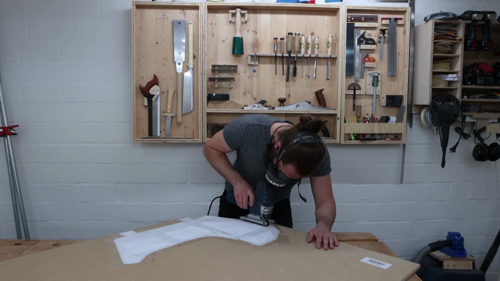
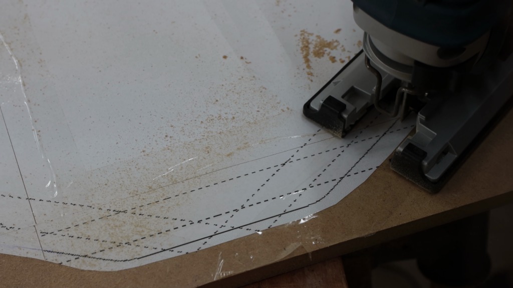
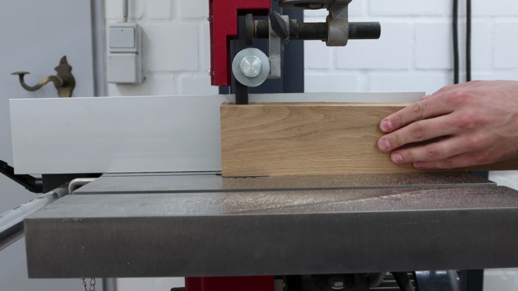
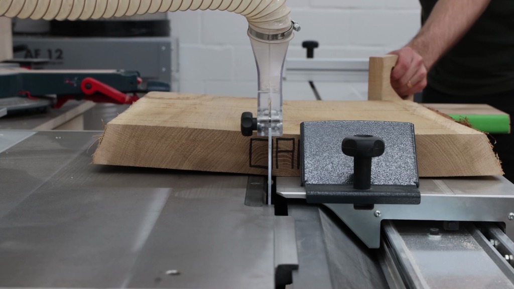
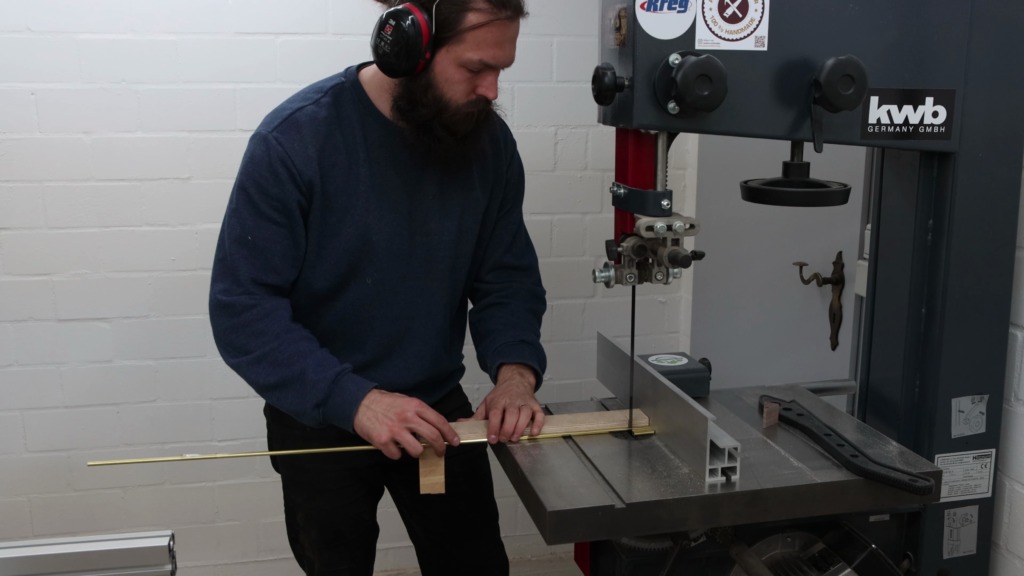
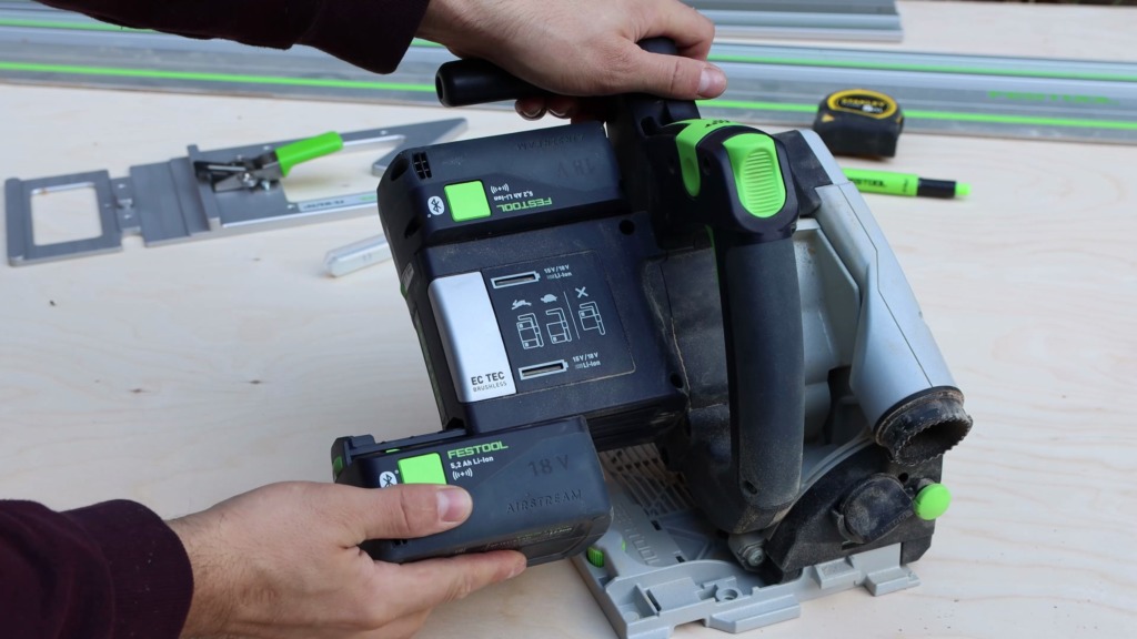
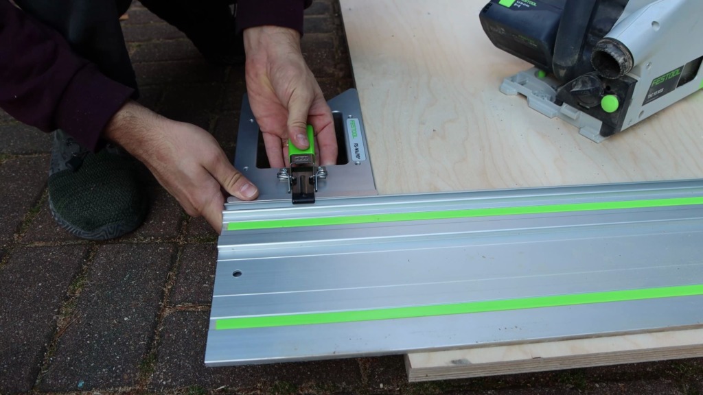
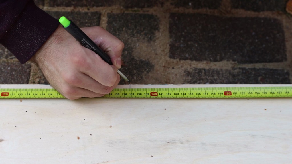
Since getting a sheet of plywood into my basement is quite a hassle, I started to break it down in our driveway. To lift the plywood off the ground I laid out rigid foam insulation sheets. For the whole project, I used 18mm birch plywood. With my cordless plunge saw, a guide rail, and a right-angle guide rail square, I established a clean and square edge on one side. I measured from there and cut the panel for the back of the rack to size, already.


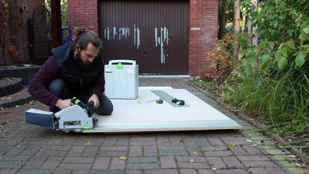

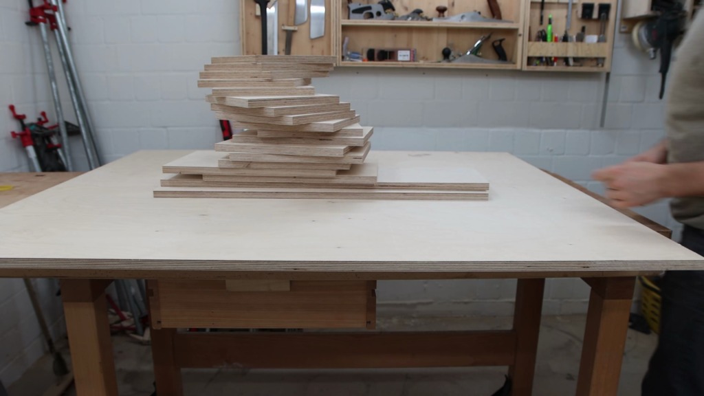
For the other pieces, I only cut the sheet roughly to size to get it into my basement easily.
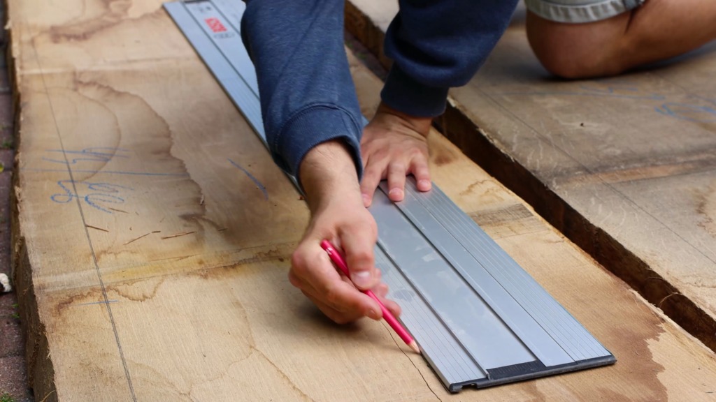
Therefore I had to rip the second sheet. My tracks are too short for that, but with a little connector, I was able to join two tracks together.


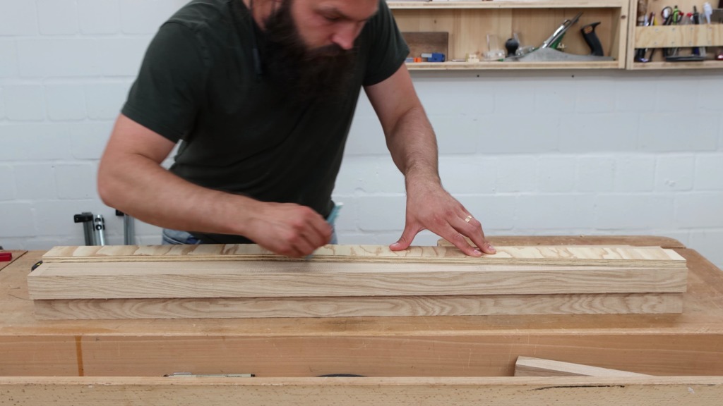
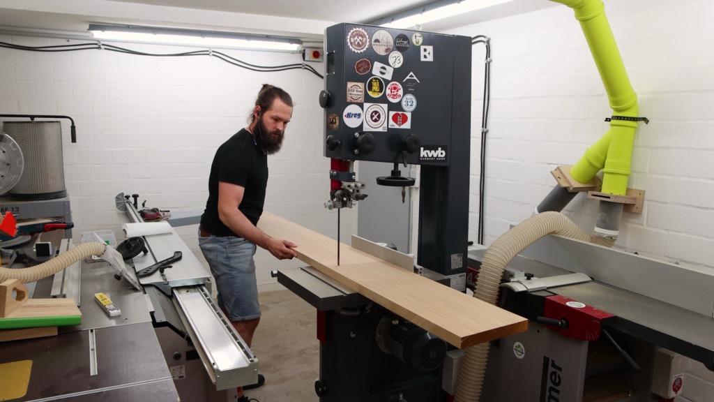
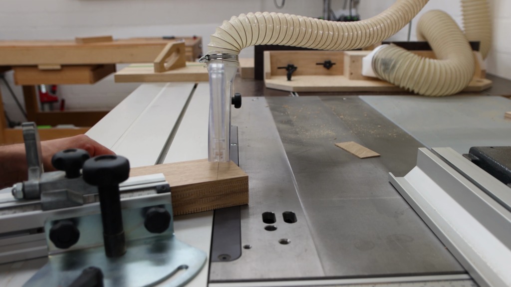
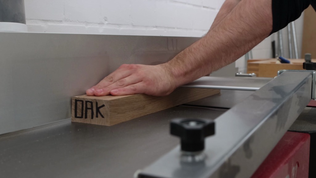
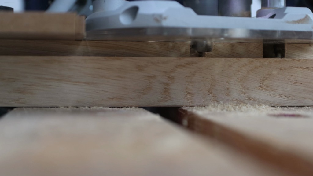
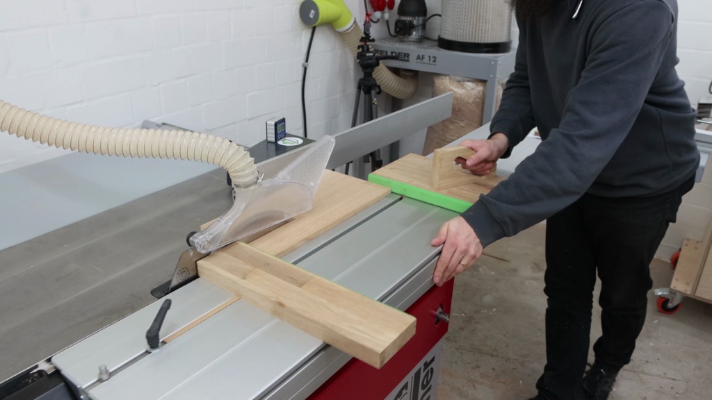
However, down in my shop I formatted all remaining pieces on the table saw.


If you want to build a clamp rack yourself, I have a full set of plans available for this project. For free. You simply sign up for my newsletter and you get the plans straight to your inbox. They include all measurements and a cutting diagram to efficiently make use of your plywood sheets. You can easily re-position the individual holders to tweak the design to your specific needs.
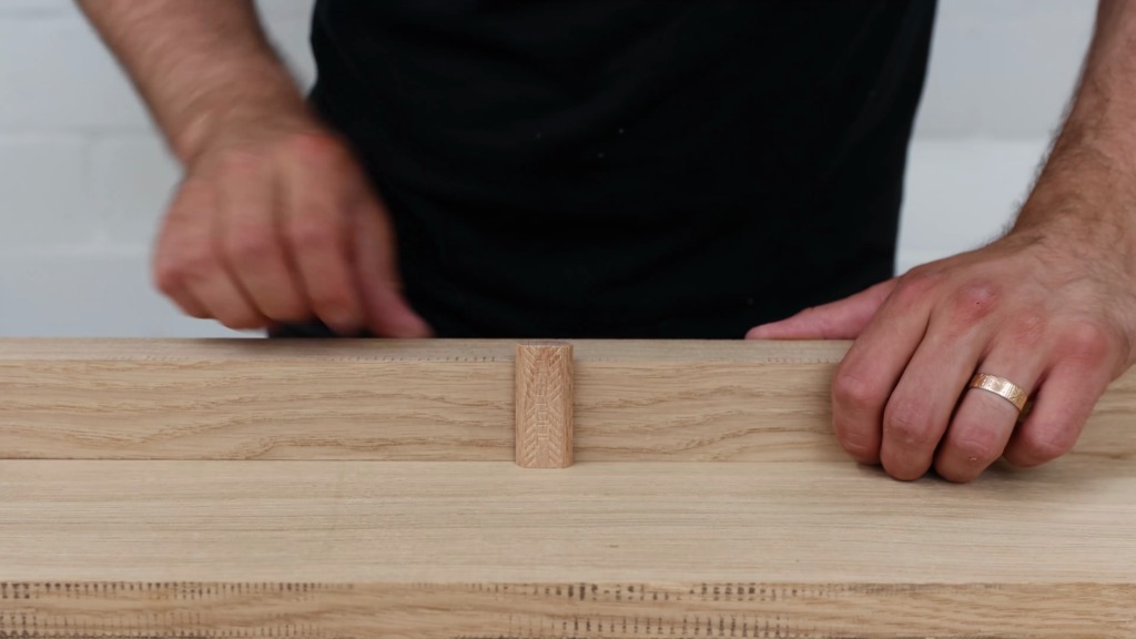
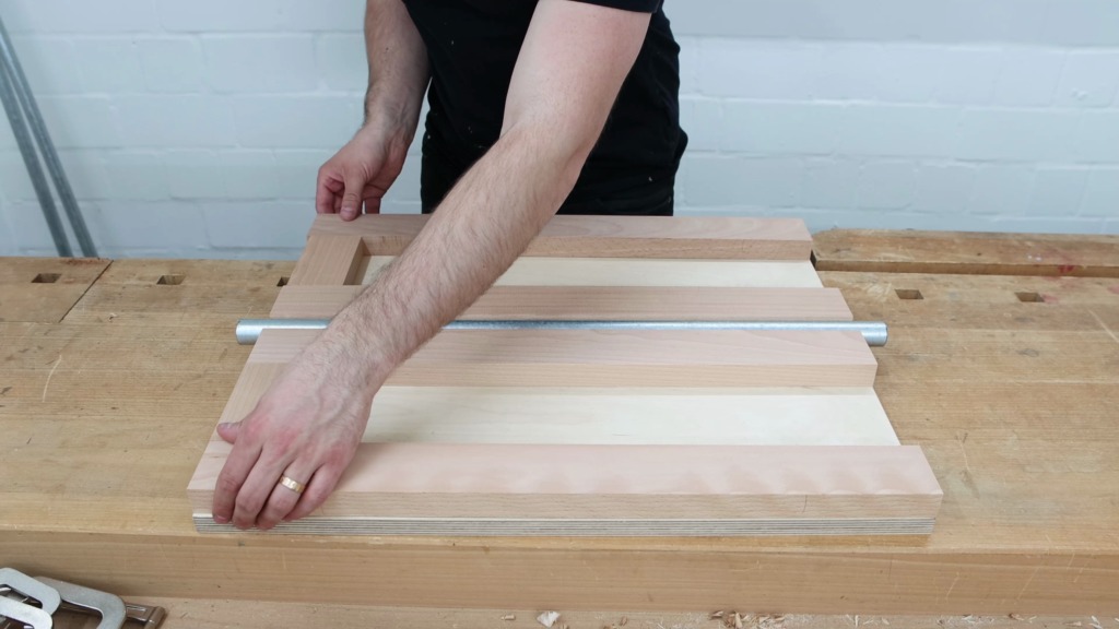
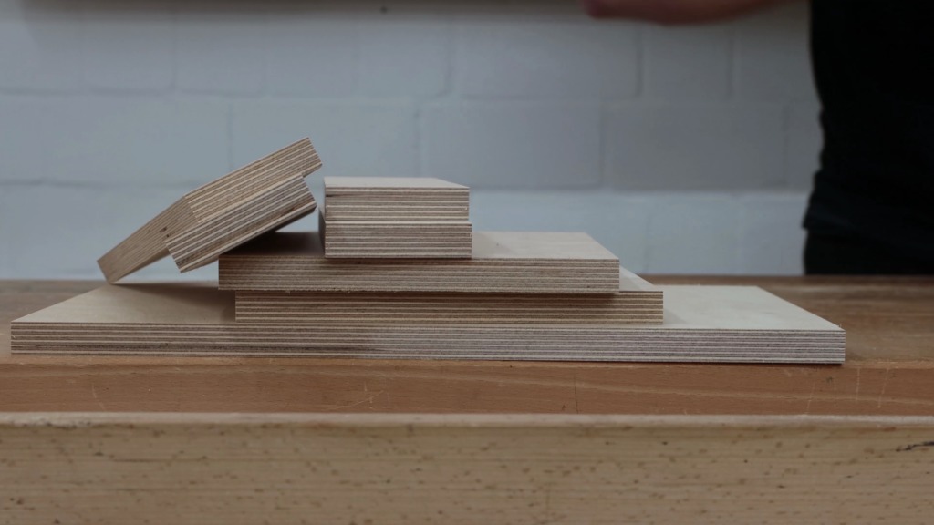
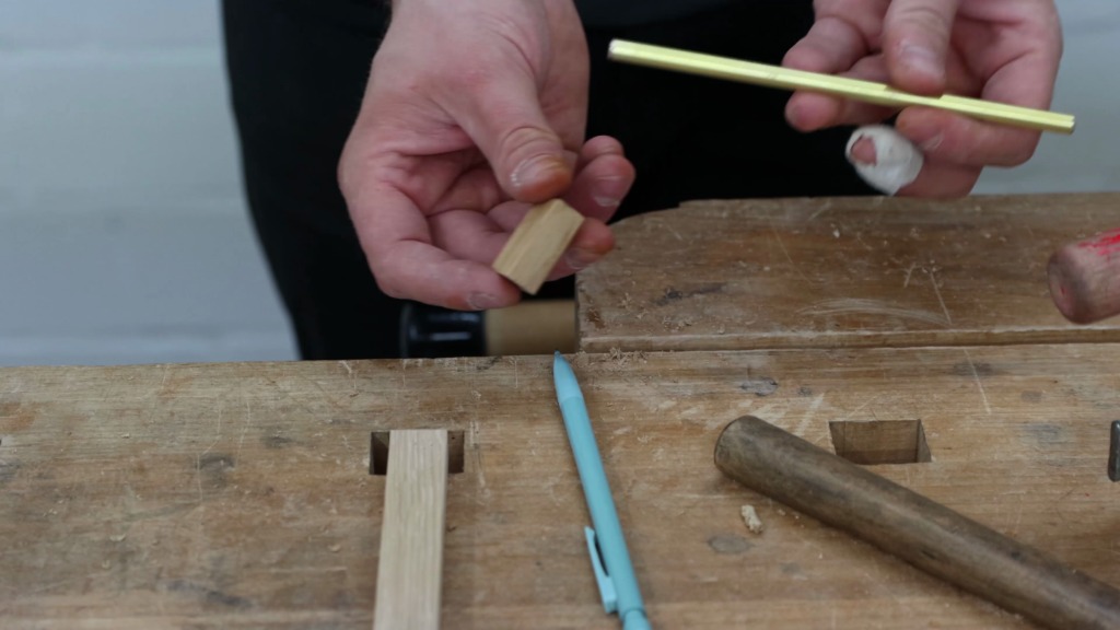
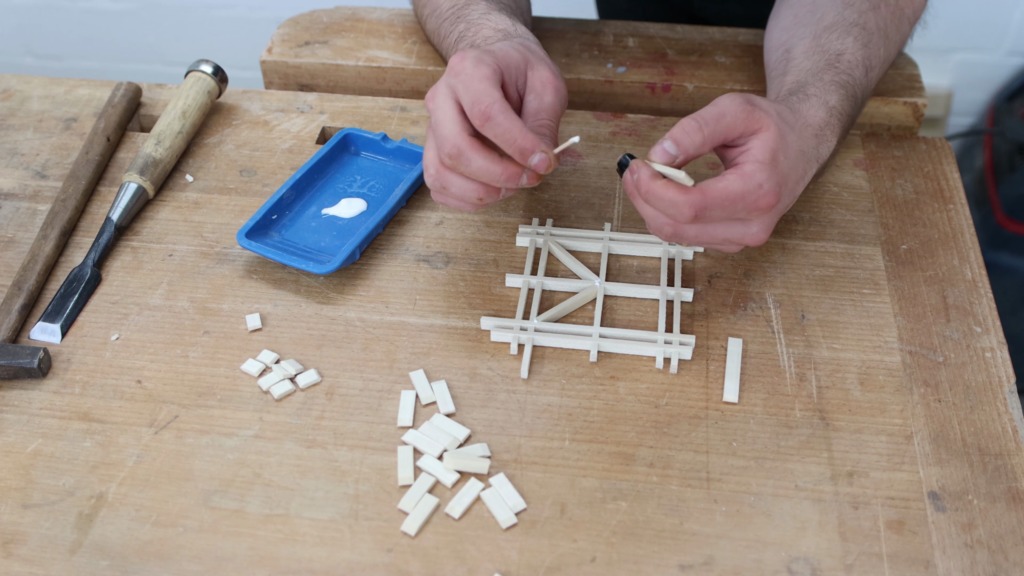
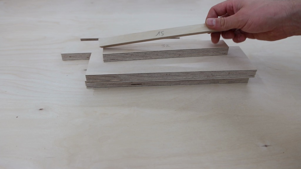
After all parts were cut I also made a series of spacers in a variety of sizes. They help me to align all the parts as you’ll see in a minute.
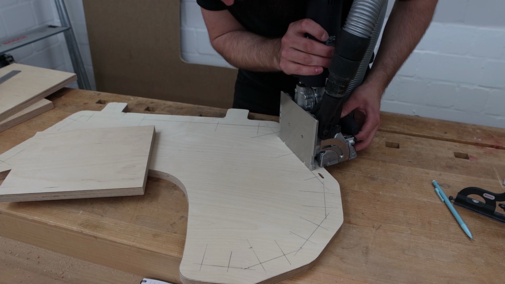
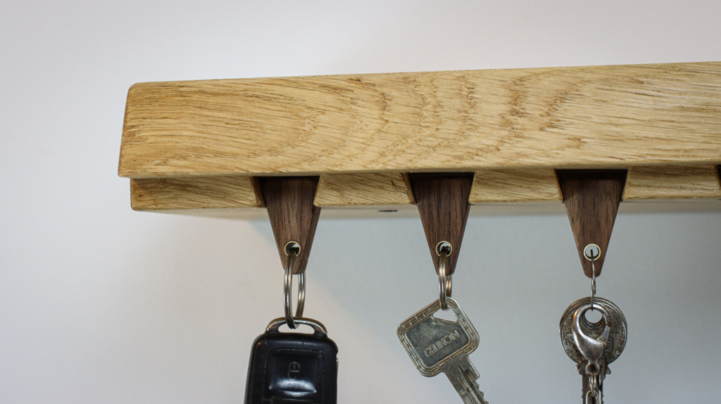
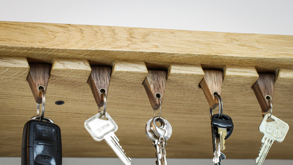
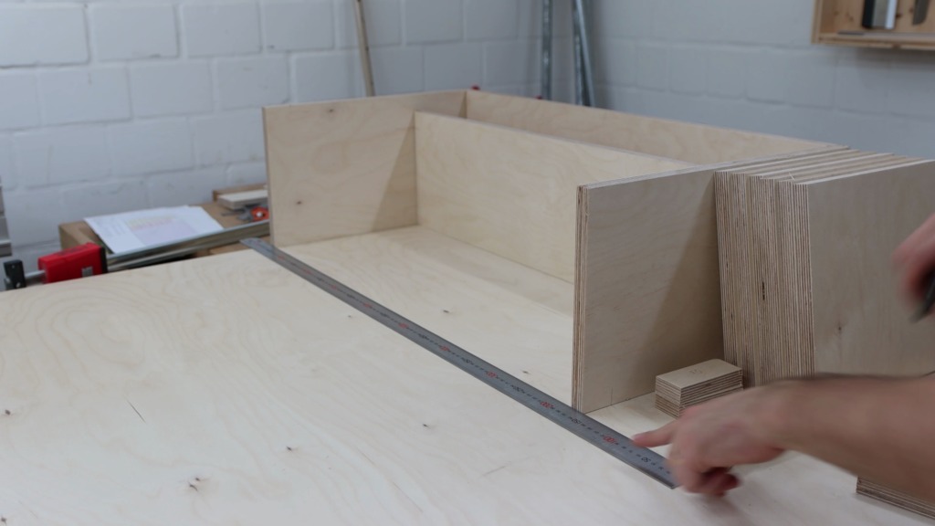
At the top left of the rack I wanted to have a shelf to put some accessories. Below the shelf they are 5 holders for parallel jaw clamps and each holder is able to hold 4 clamps.
Joinery
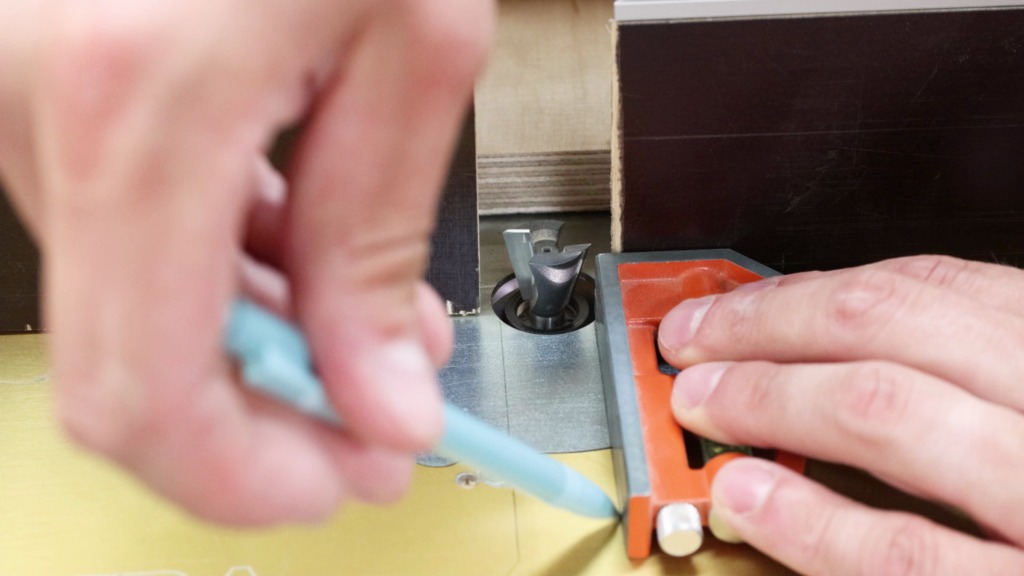
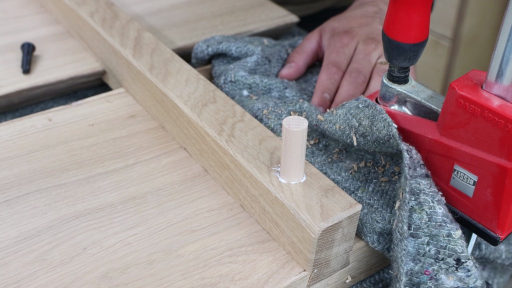
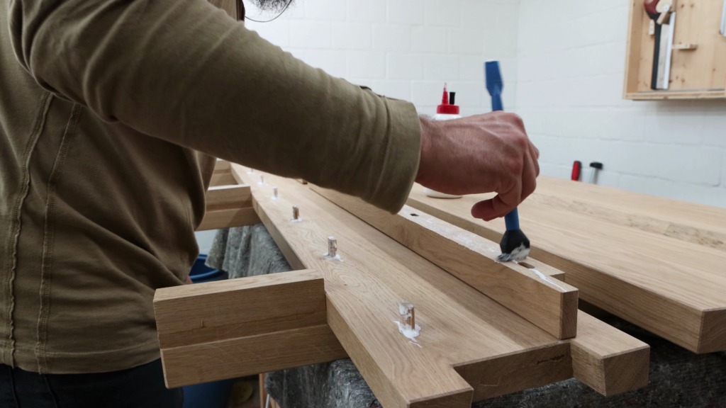
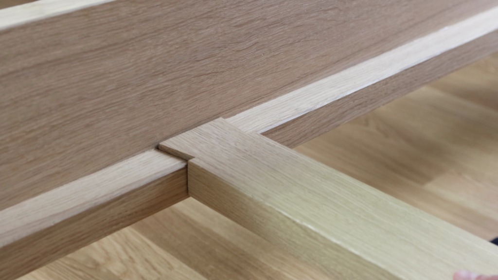
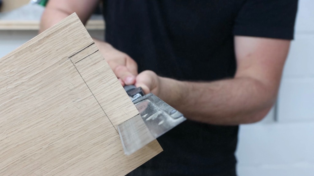
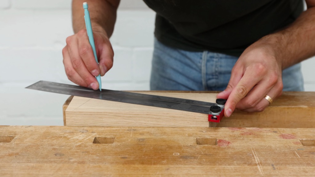
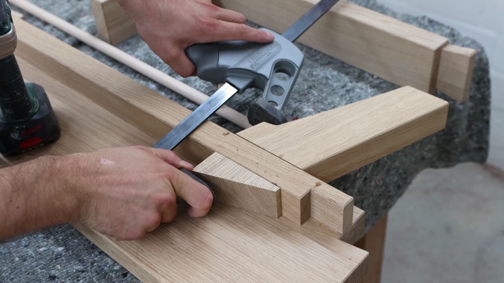
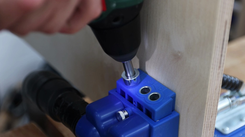
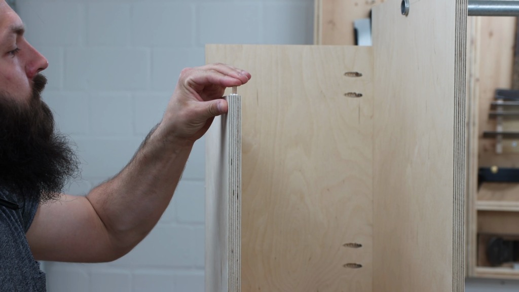
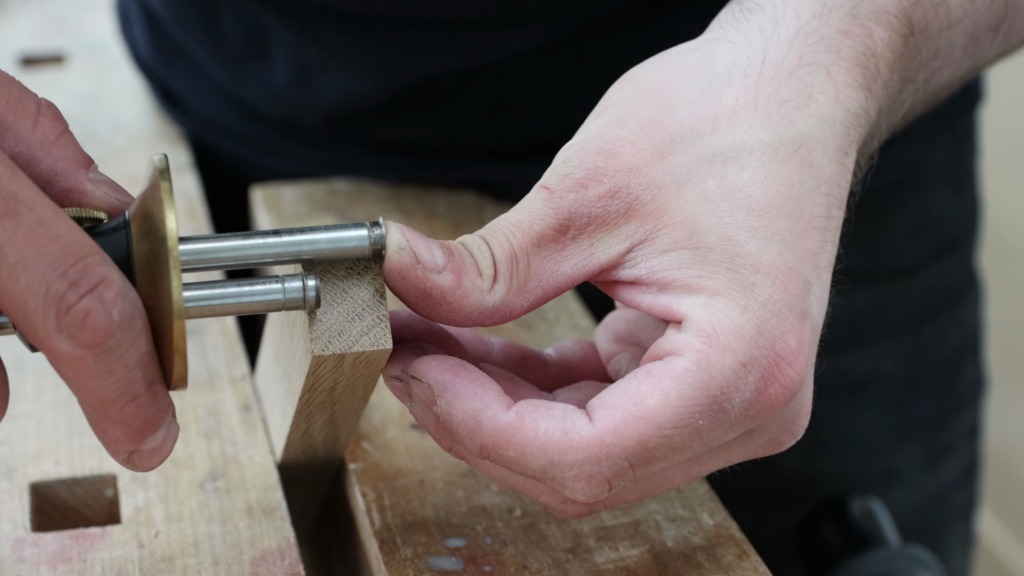
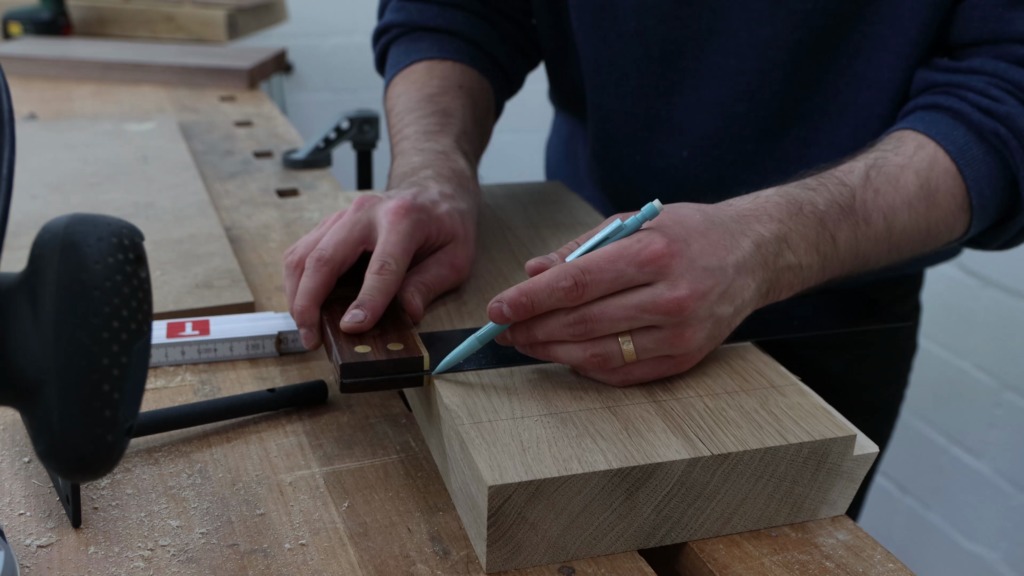
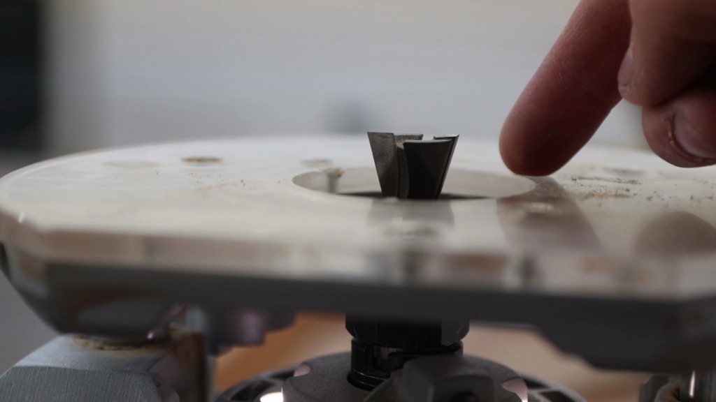
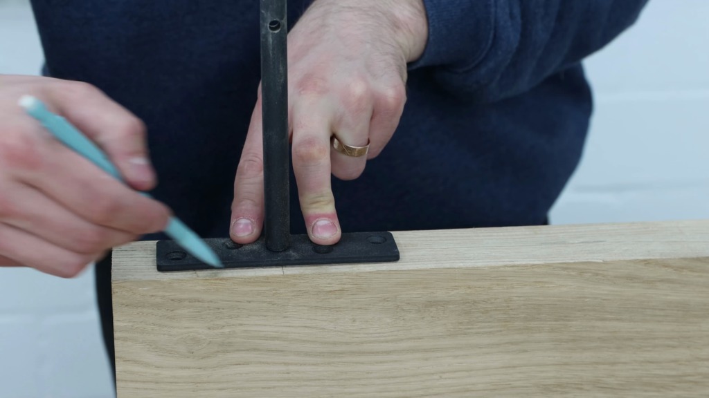
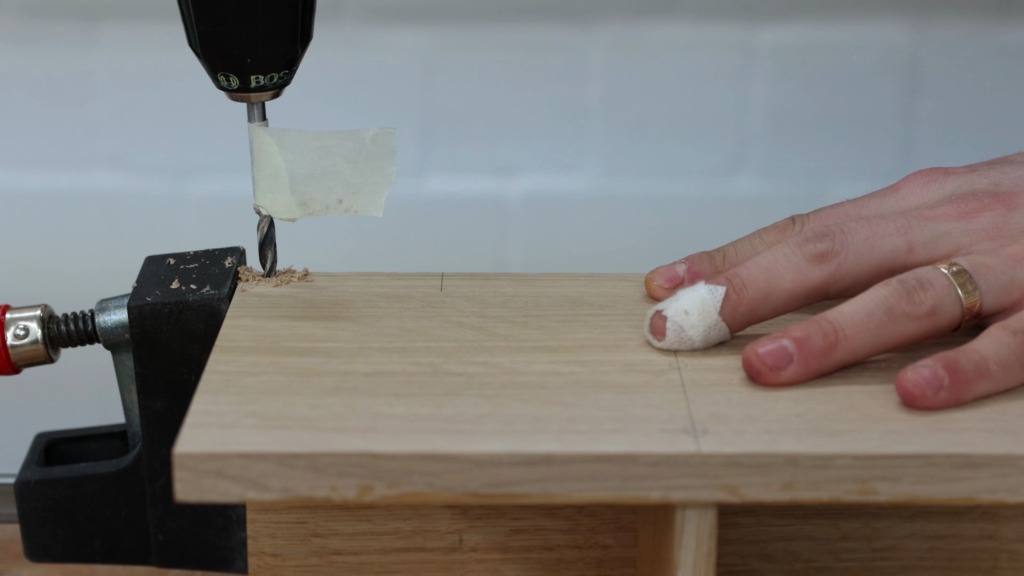
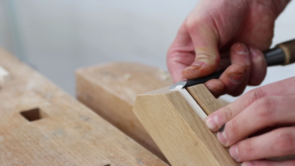
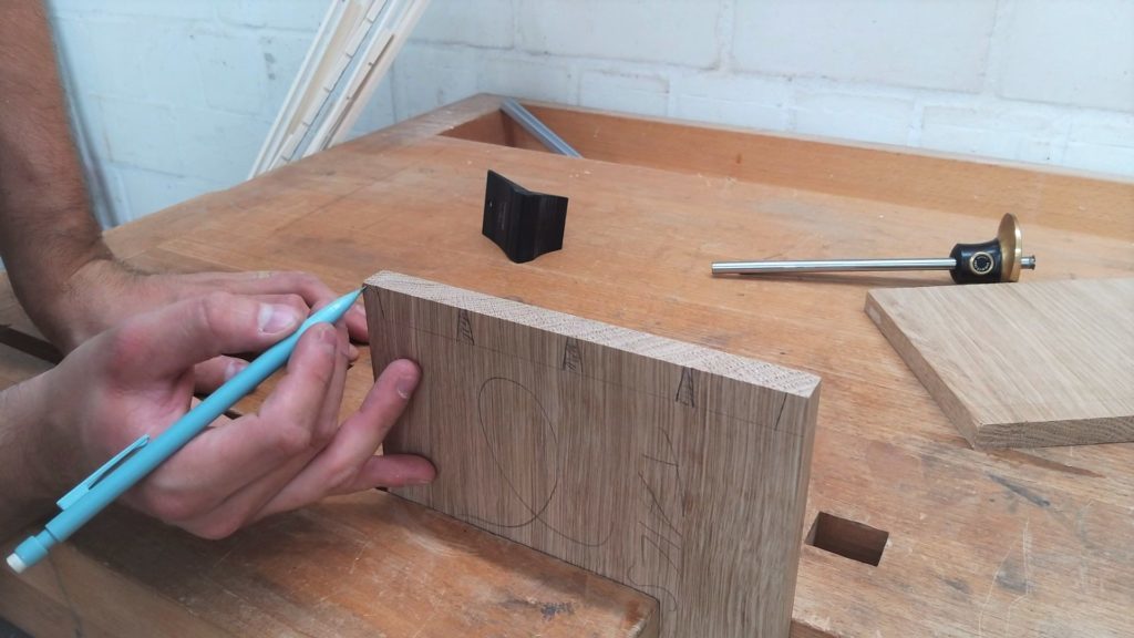
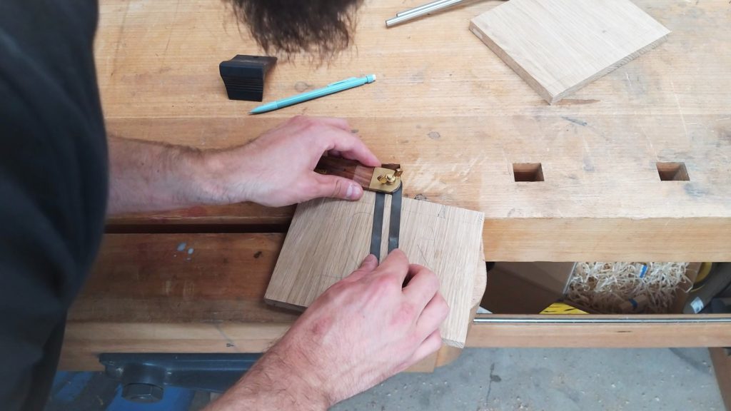
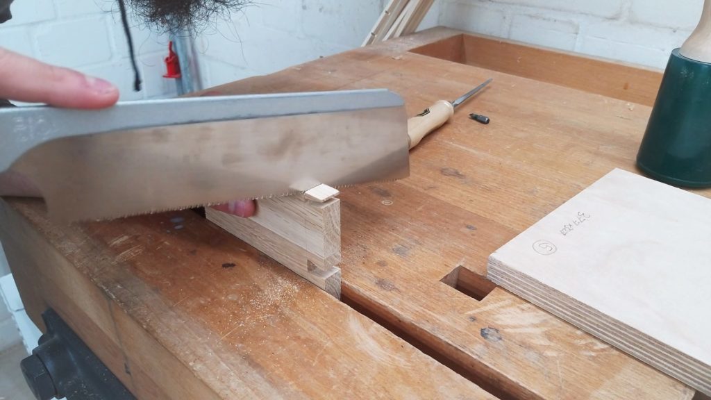
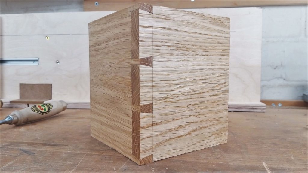
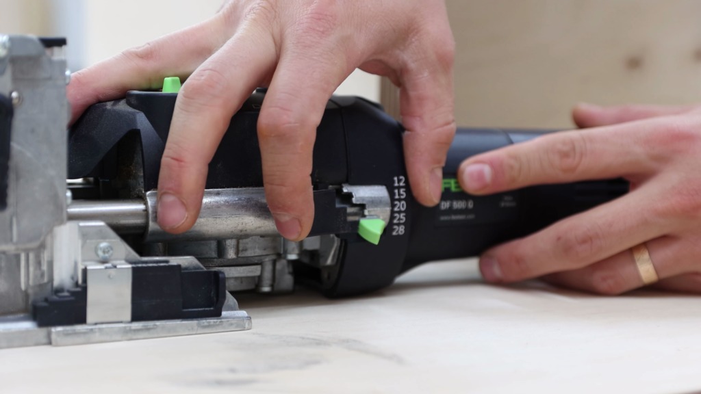
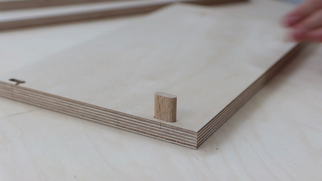
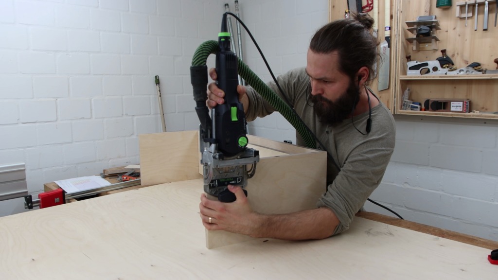
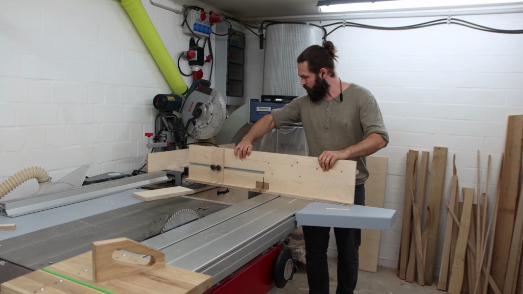
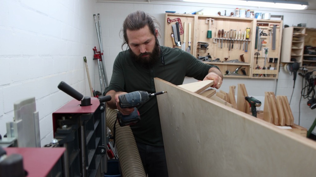
For the joinery I decided to go with Dominos, which are floating tenons. Therefore I had to mark where to register the Domino.
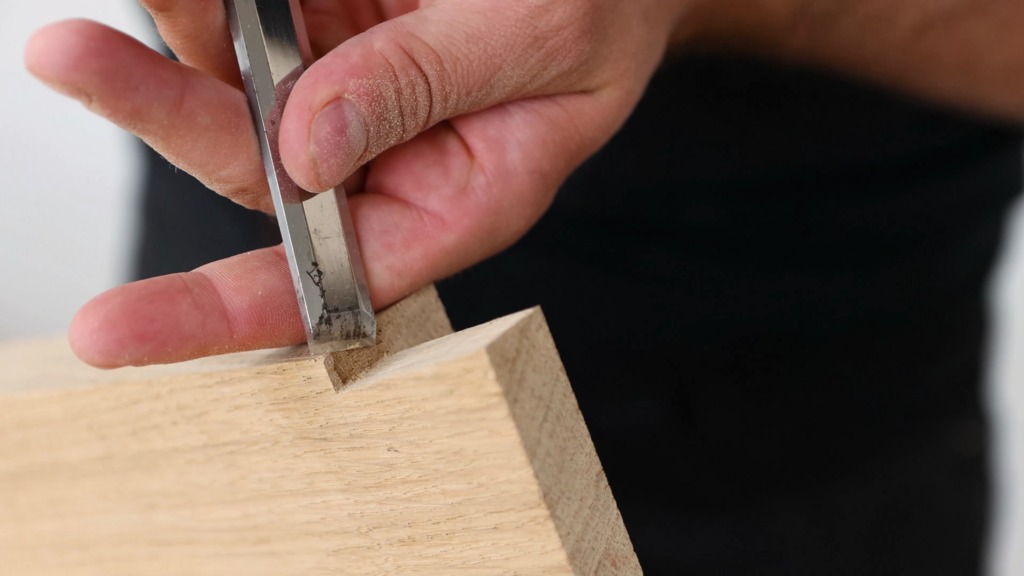
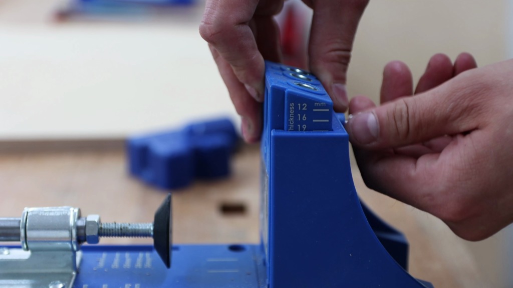
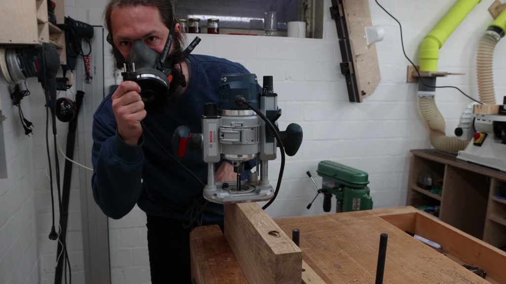
Marking the top of shelf was easy and placed all Dominos in this project without measuring. The Dominos I used were 8x40mm and hence routing 20mm in each part would end up with proud Dominos on the parts where the slots are routed into the face side, since the plywood is only 18mm thick. To accommodate for that I routed 25mm into the edges and only 15mm in to the face sides.
I set the fence of the Domino to the closest of 18mm which was 16mm, attached the vacuum and plugged it in. Routing the recesses was pretty foolproof at this point, since I only had to align it to my marks. Before routing into the face sides I switched the depth setting to 15mm.
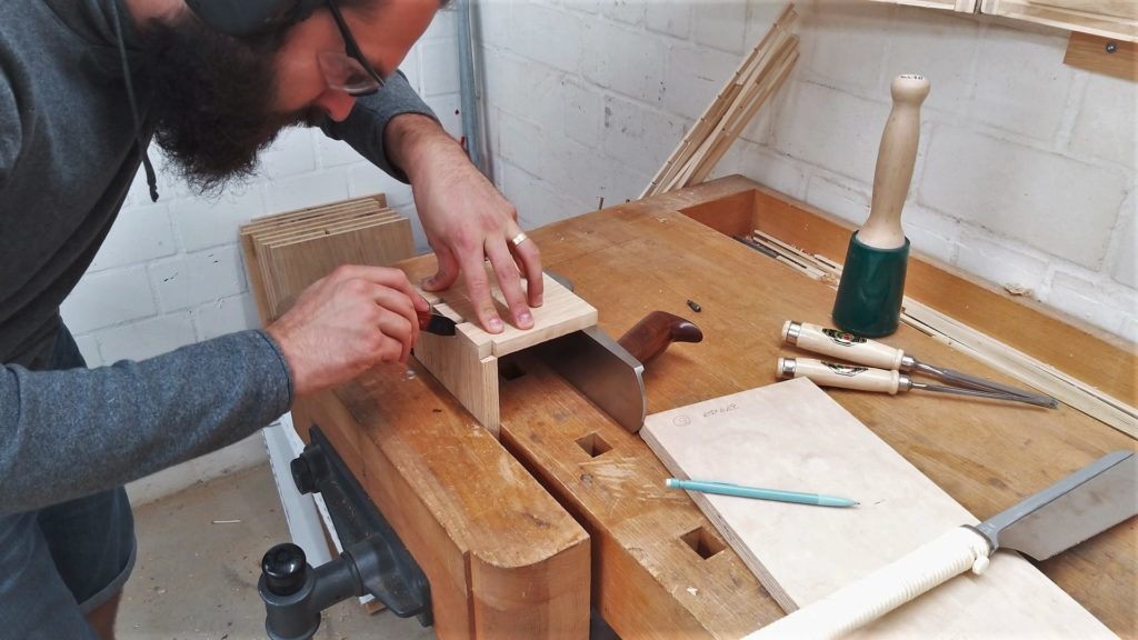
What I really like about this joinery method is the fact that dry fitting is pretty comfortable and I can temporarily assemble the piece. Granted getting the dominos out can be a challenge sometimes. But with a set of pliers, they all come out eventually.


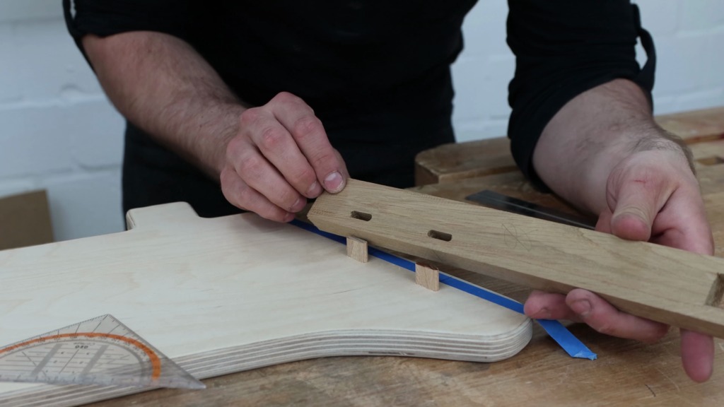
To position the shelf I used a pair of spacers and put the shelf board on top of it. I stroke a line, where the base of the Domino will be registered against and some tick marks with the head of my combo square.
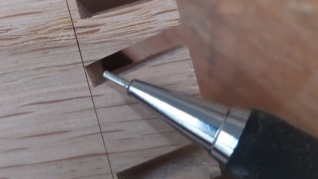
I registered the Domino against my line and routed the slot. After switching to 25mm and flipping the fence over I made the counterparts.


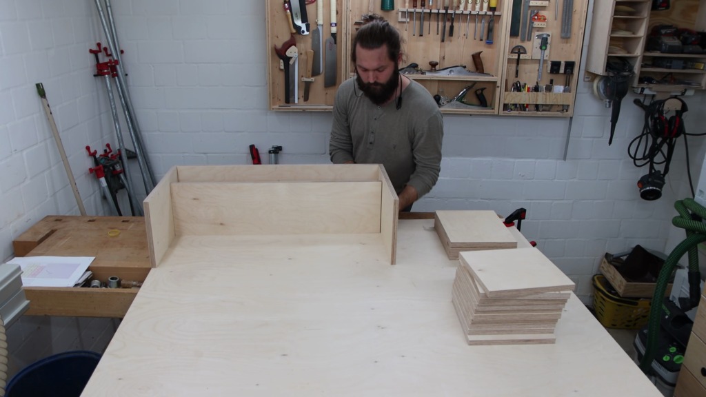
No surprise as they fitted perfectly. To really hold everything in place I used a parallel jaw clamp. I positioned the shelf unit flush against the top and side, made my marks and routed the slots to attach it to the back of the rack.


Clamp holders
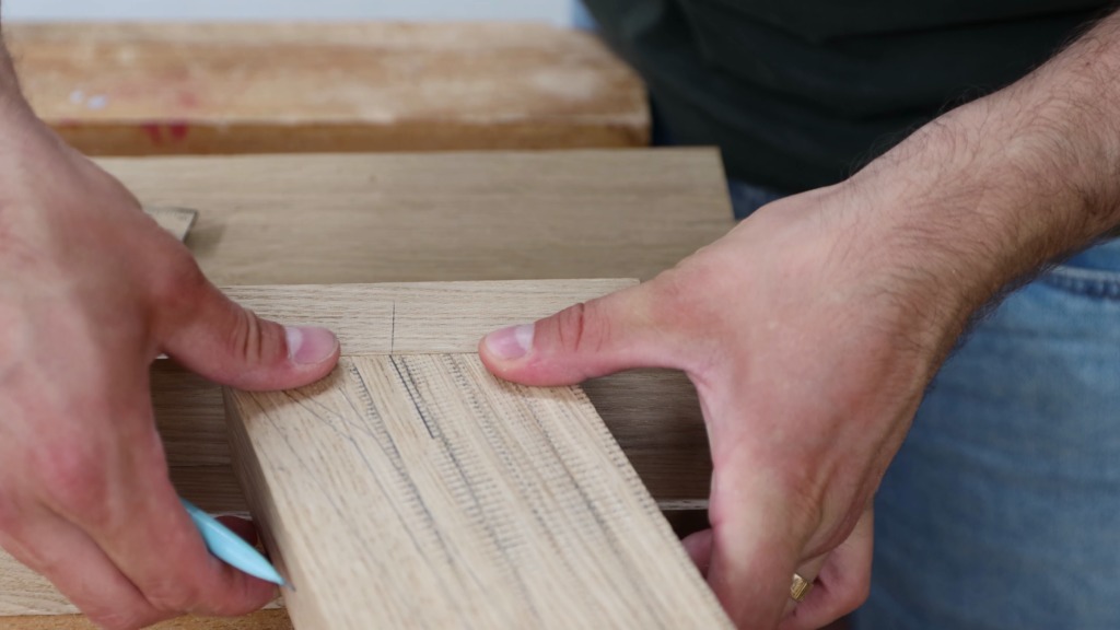
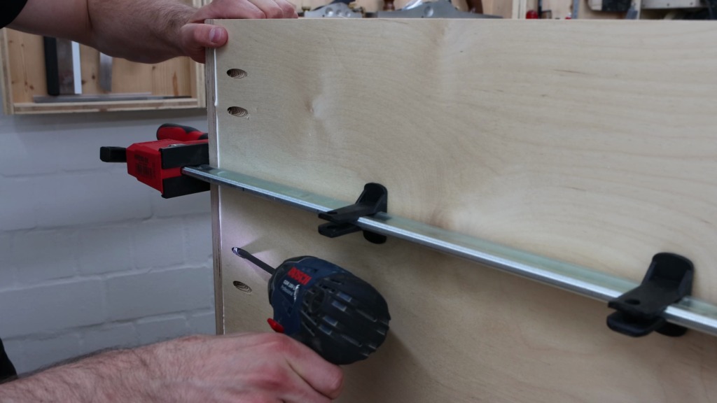
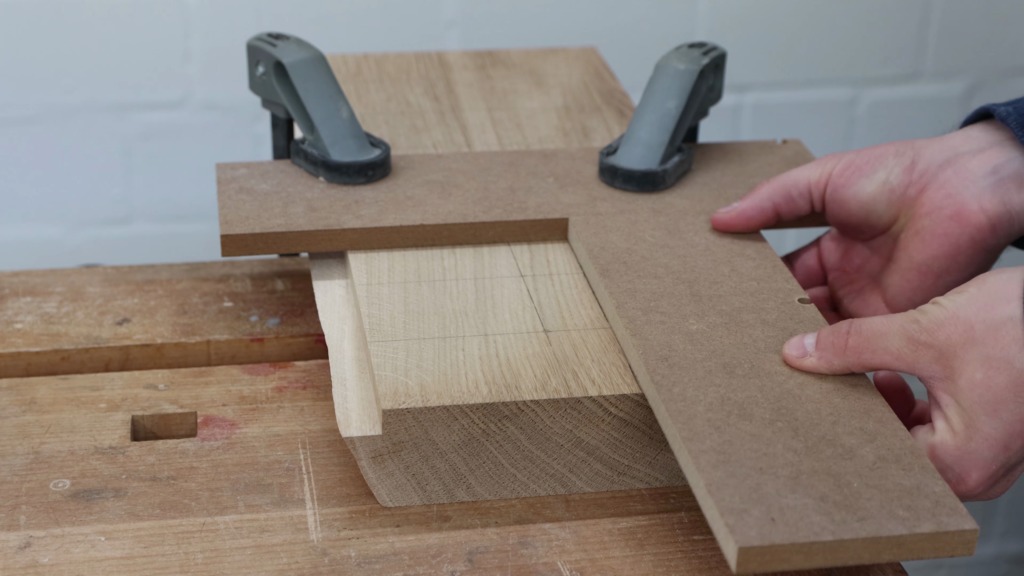
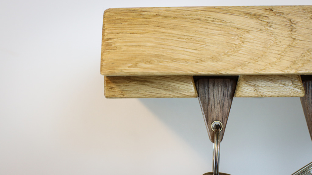
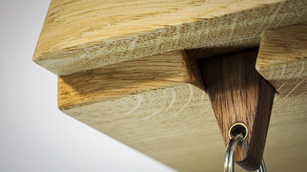
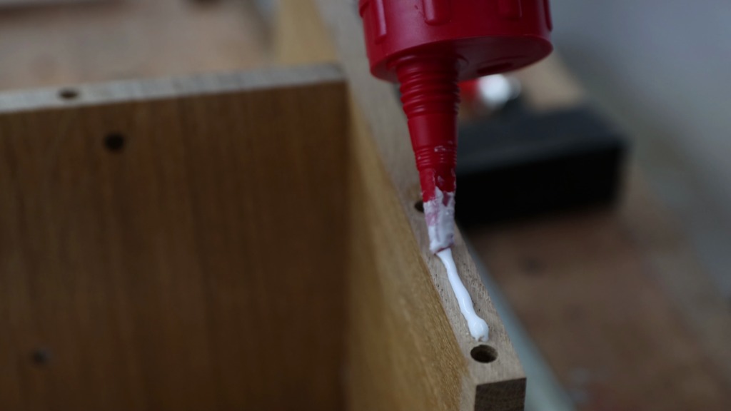
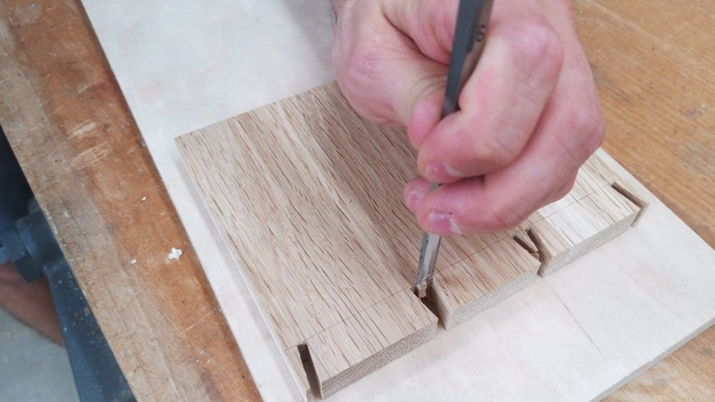
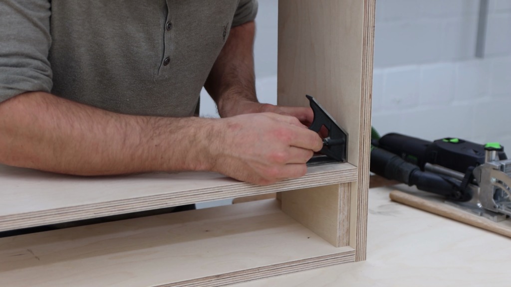
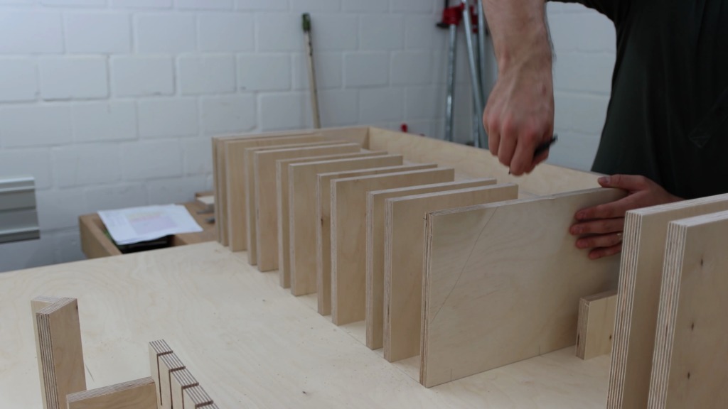
I stroke another line that indicates the bottom of the holders for the clamps. With the help of the spacers I could temporarily put the holders in to place and mark them as well as the back for the Dominos. I did this with the whole row of holders.


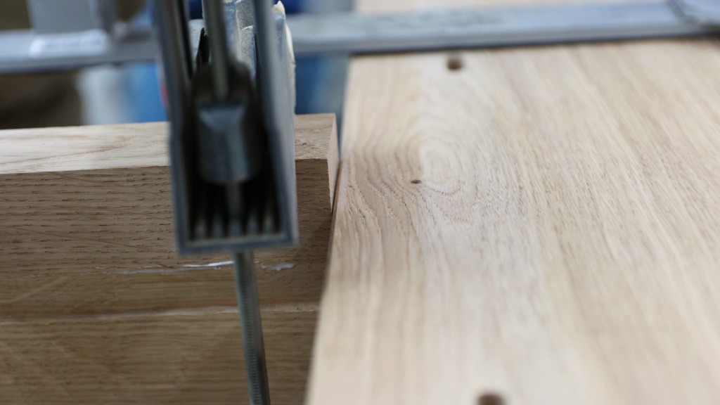
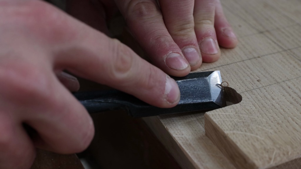
Then it was just a matter of batching out the Domino slots. In the back panel as well as the holders themselves.
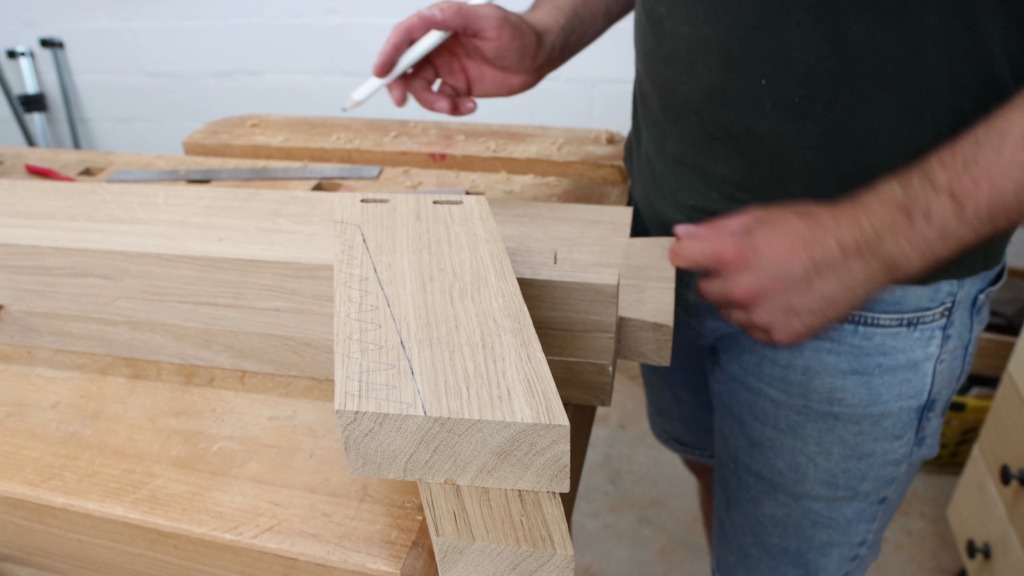
On the right side of the rack I positioned another two holders for my pipe clamps.
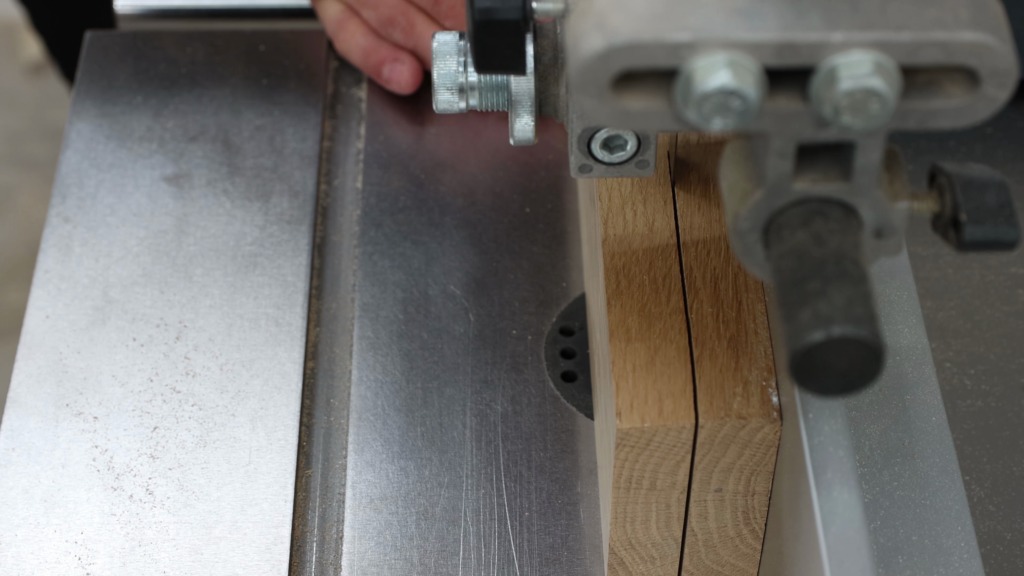
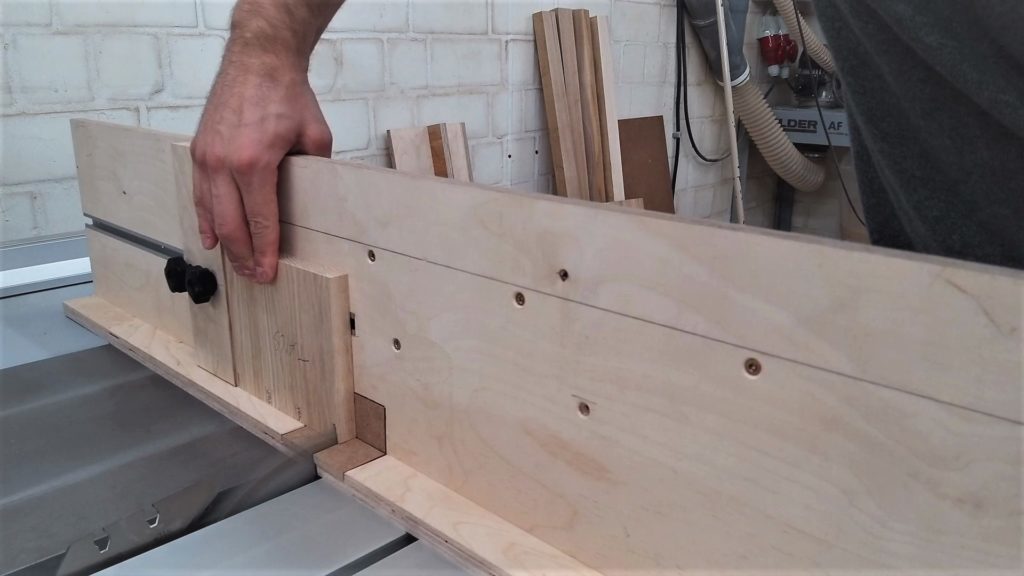
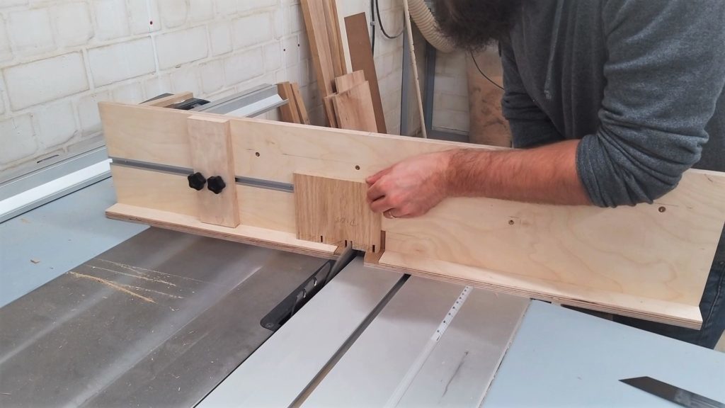
In the center I wanted to have a bunch of different holders for all my special clamps, like one handed clamps and band strap clamps. I marked a couple of slots on a cut-off piece and turned to the table saw, where I set up the jig I use to make dovetails on the table saw. If you haven’t seen that video you might want to check it out. It’s a pretty cool way to batch cut dovetails. Anyways I lined up my marks with the blade, set the stop in place and made my cut. To widen the slots I put a wood strip as a spacer between my workpiece and the stop. That strip is exactly as thick as my saw blade.


To the side of the holder I attached small squares that make it more rigid. I used the same techniques as before to attach the holders to the back panel.
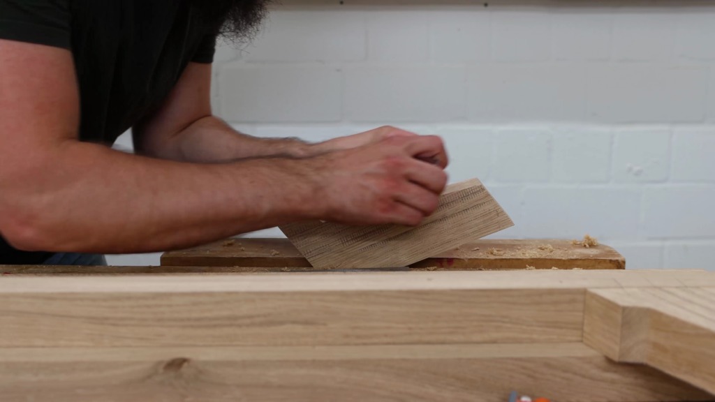
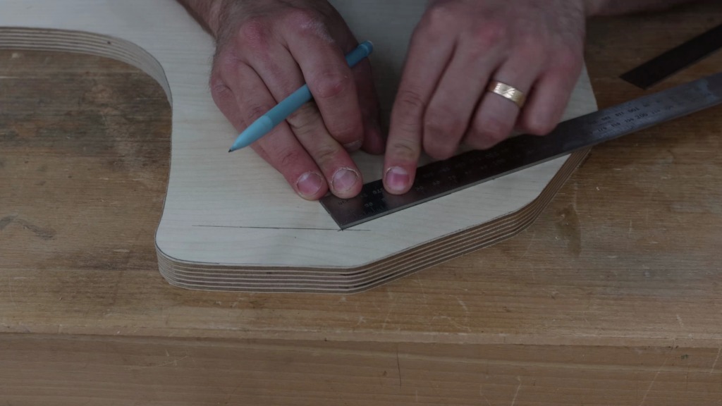
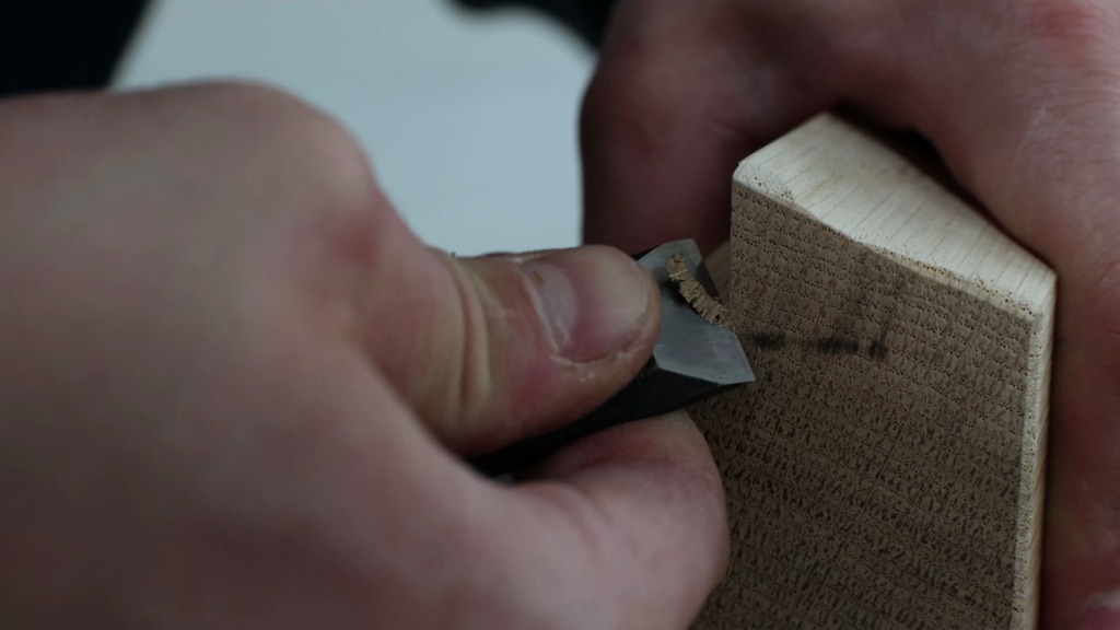
For the band strap clamps the holder was fairly easy. Just two cut-off strips glued together at 90° which function as a hook for up to 4 clamps. I know this step is absolutely not necessary but I wanted to position the holder precisely square to the edge of the back panel. I made a tick mark where the holder roughly should be. With a large square I drew a line square to the edge and in the center of the holders new spot. With a triangular ruler you probably remember from math class, I could mark the outside edges of the holder. Then it was just a matter of following the same process as for all the other holders.


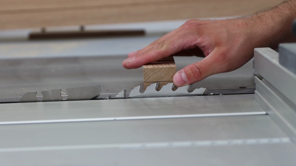
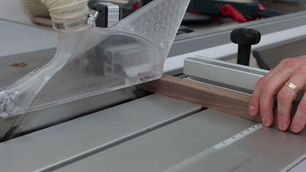
To give the holders for the parallel jaw clamps a bit of a nicer look I decided to cut-off the bottom corner at 45°. Since I like to mess things up, I marked every single piece. Over at the table saw I set my miter gauge to 45° and cut two pieces at a time.
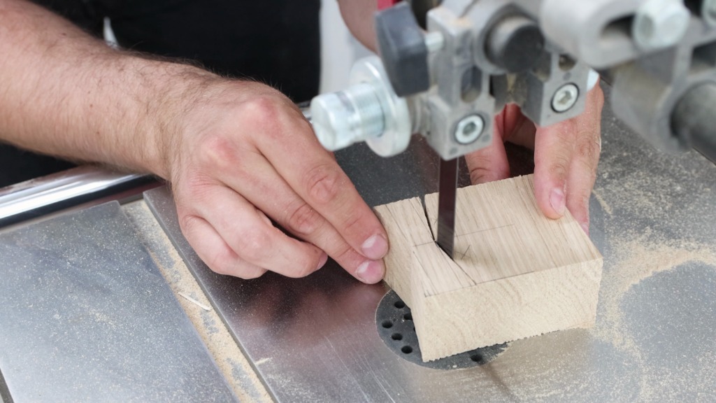
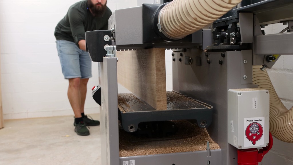
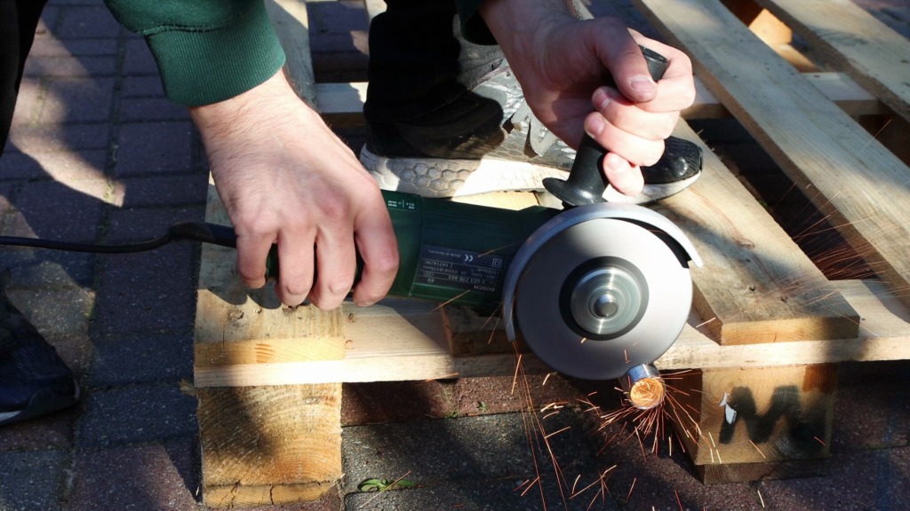
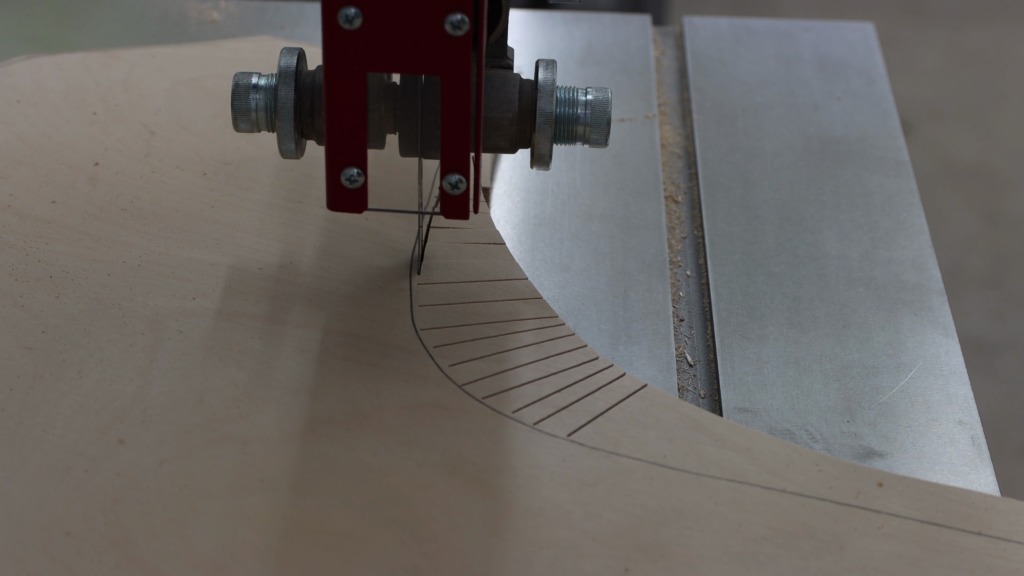
Parallel jaw clamps are pretty heavy as you might know. I am not very keen on having them rain down on me because I bumped into them. I small hook on the holder should do the trick. I made a rough, very rough sketch on how they should be. I positioned my fence of the band saw according to my mark and clamped an off-cut as the depth stop to the table. That gave me the first part of the hook. I removed the provisional depth stop and made the second cut.


Surface prep and finish
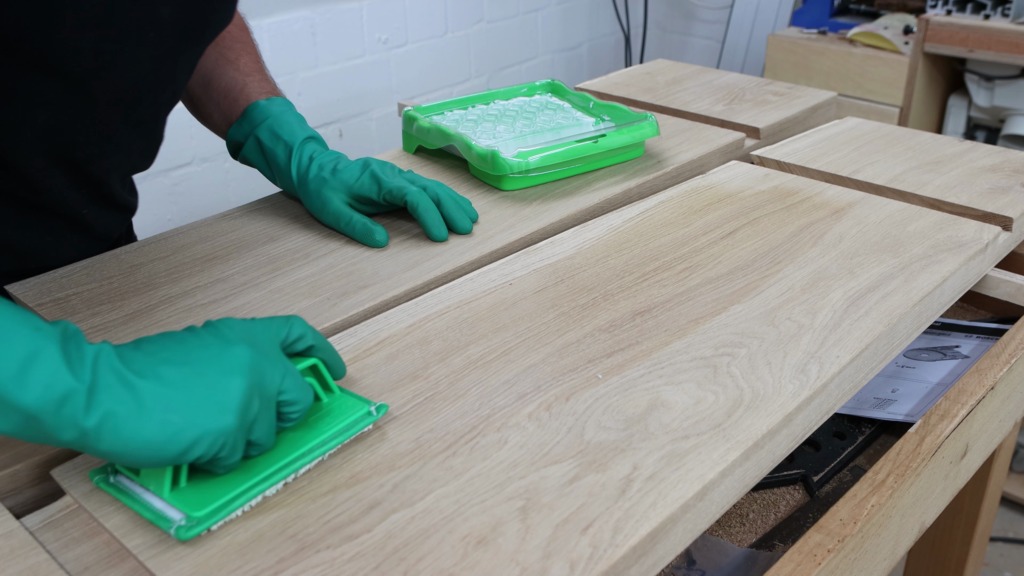
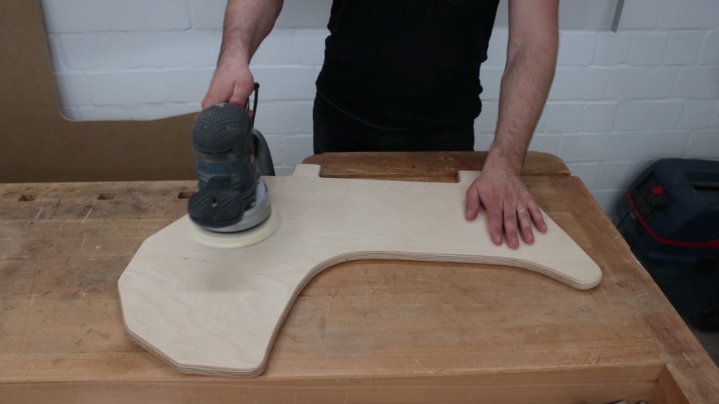
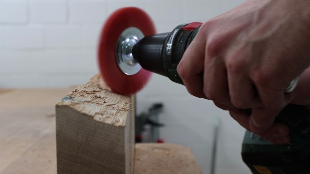
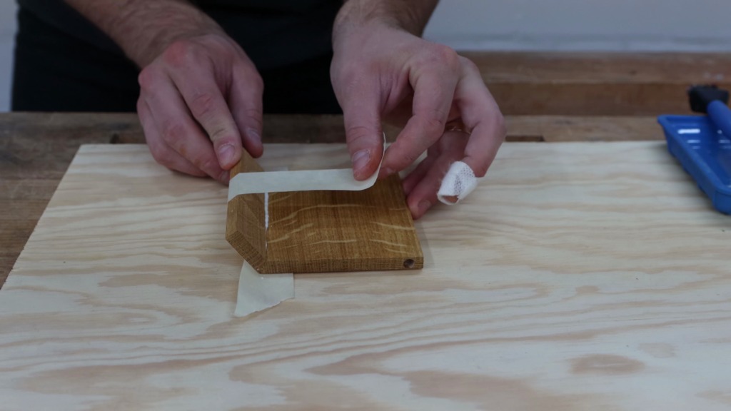
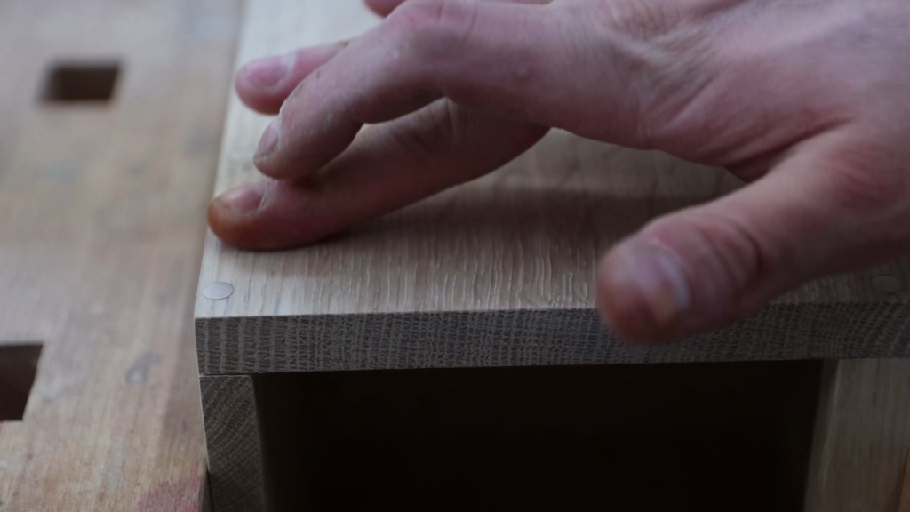
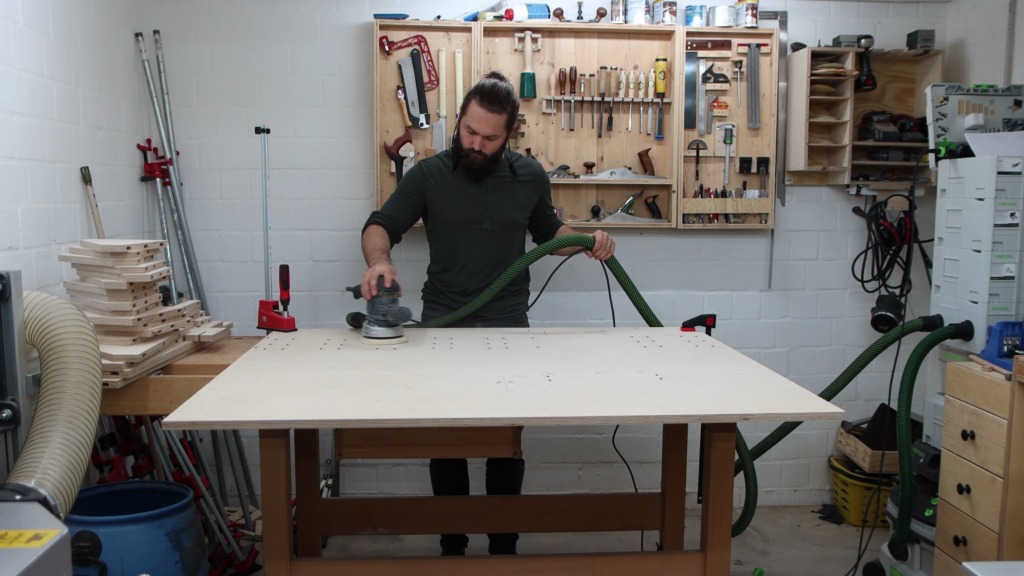
For this project I opted to put finish on the parts before the glue-up. So many inside corners make it really hard to get finish in there. I sanded with 220 grid to get rid of my pencil marks and have a smoother surface. I made sure to not sand through the layer of ply. Been there, done that, not cool.
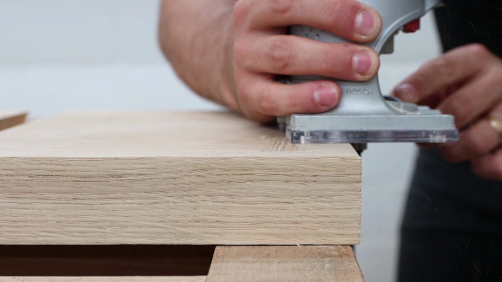
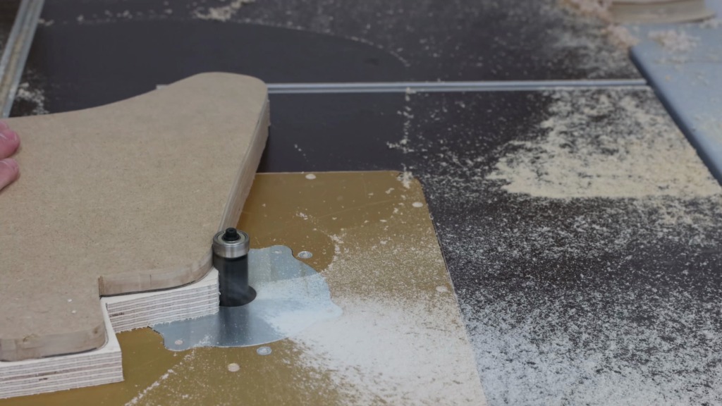
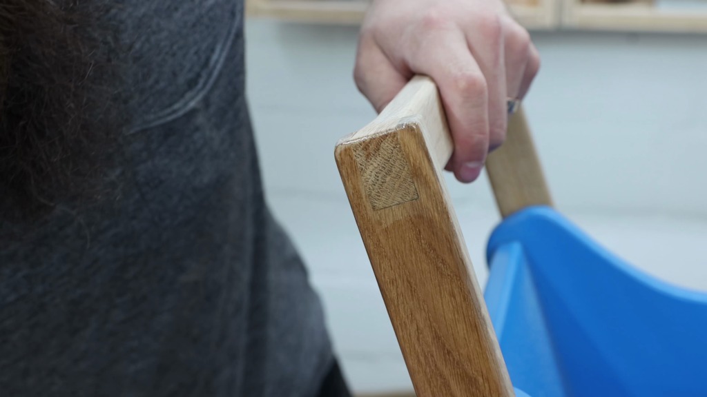
With the router I gave all edges a small chamfer.
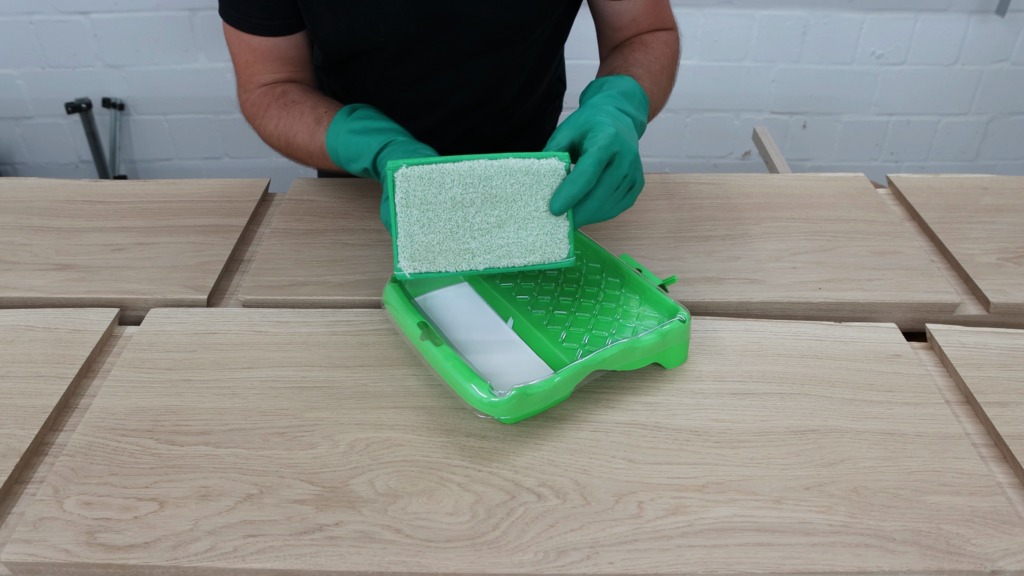
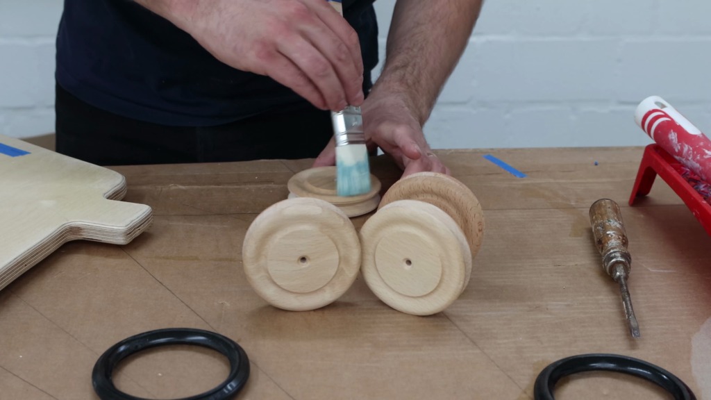
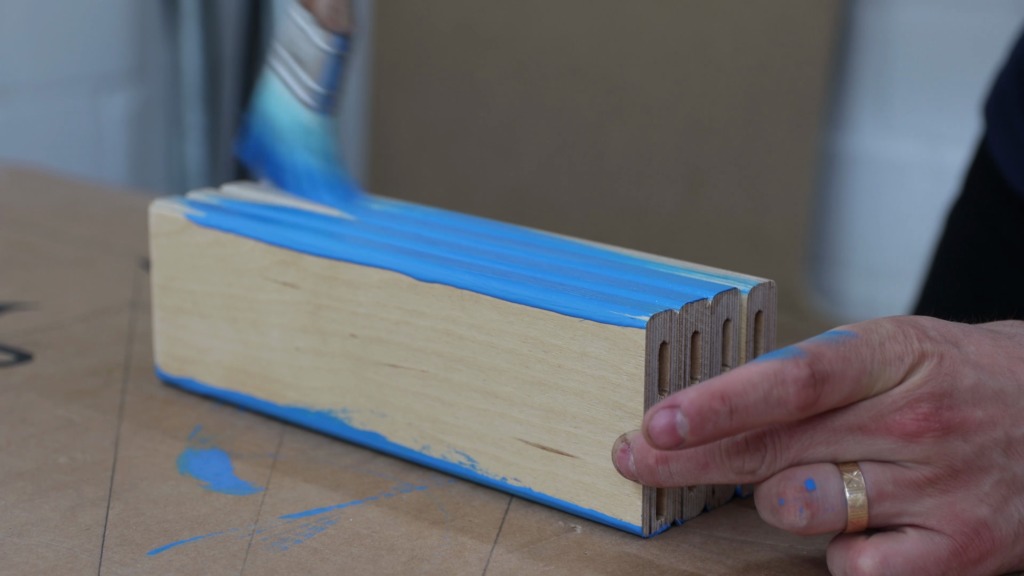
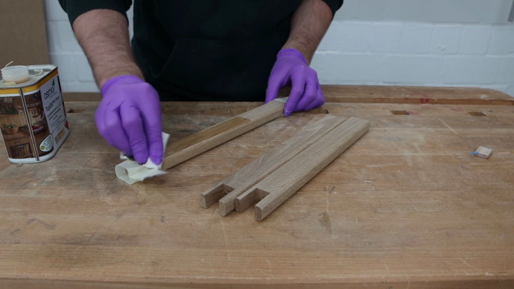
For the finish, I went with Osmo’s TopOil (or PolyX depending on where you’re located). When applying it with the hand pad I avoided the areas that became glue surfaces later on, since the glue wouldn’t stick as well.
I applied just one coat since this is a shop project.
Make sure you are subscribed to my channel and turn on the notifications by hitting the bell icon. I have a bunch of cool projects lined up. For the shop as well as furniture pieces.


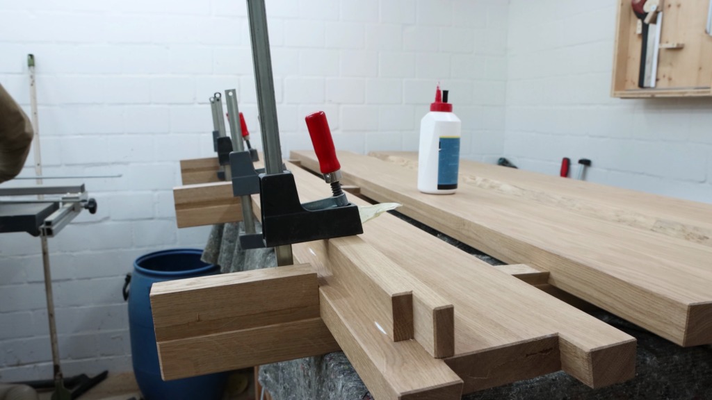
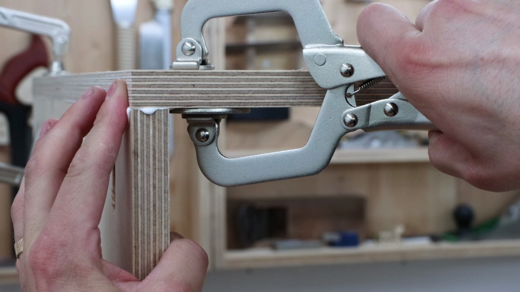
Glue-Up
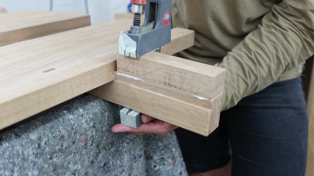
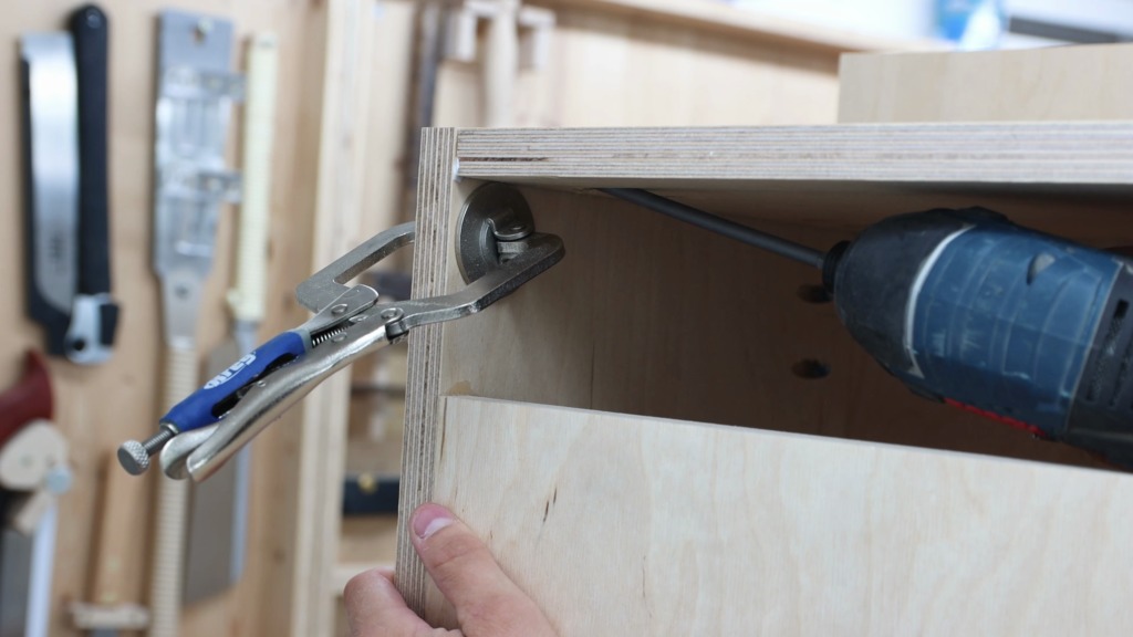
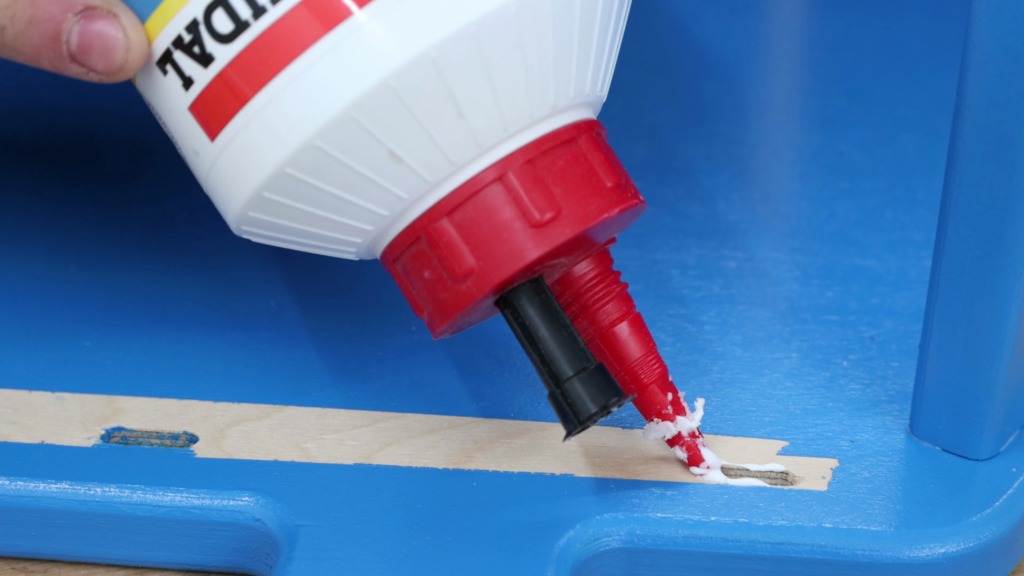
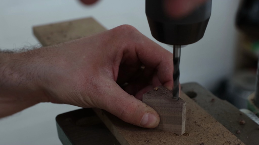
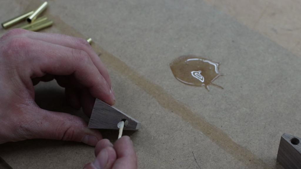
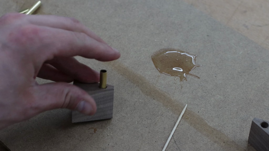
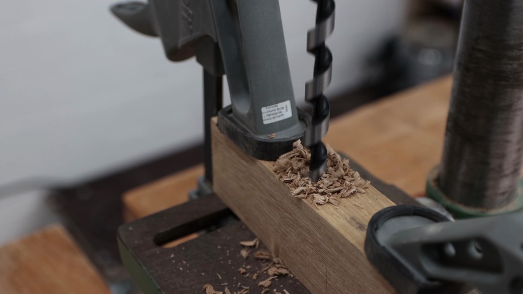
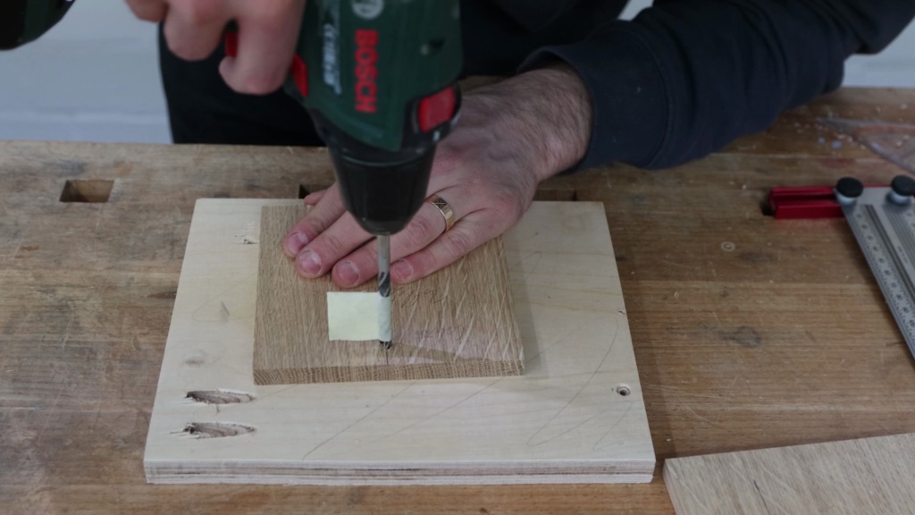
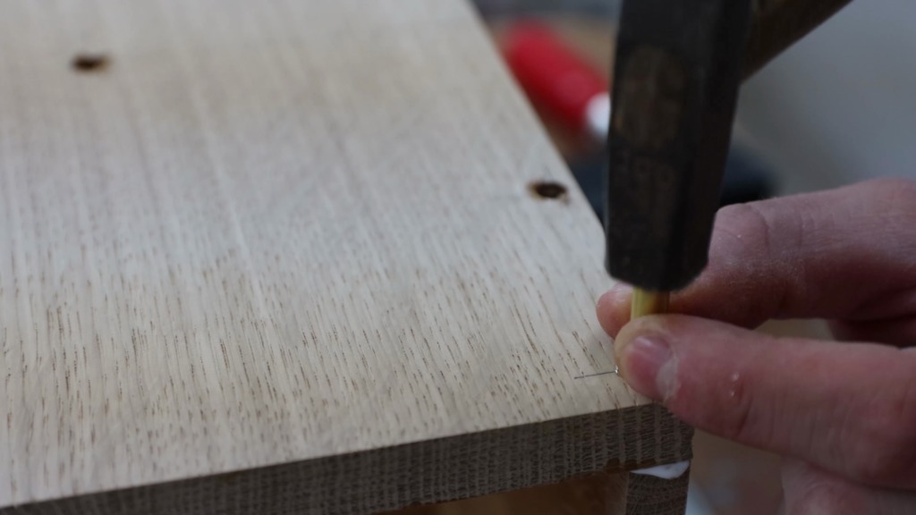
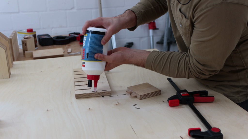
After letting the finish dry overnight, it was time for the gluuuueee-up. I know it’s paradox but I pre-drilled holes for screws that act as clamps, so I won’t have to clamp the parts of my clamp rack. It would have been a pain to get clamps on for all the holders…
Glue in the Domino slots, insert the Dominos, glue on the holder, spread it a bit and then put the holder in place. Through the holes I drilled earlier I pre-drilled the holder as well. Notice the stupid look you have to put on when eyeballing the angle. Super important! I drove in 2 screws per holder.


With the rack on my workbench again I glued the remaining holders to the back.
When gluing the shelf to the back it was at this point I realized I forgot to put glue on. So I put glue on and gave it another run. Somehow I struggled a lot to get that thing together. But a few taps with the mallet and hammer made me a happy wooodworker. Again I used screws from the back.
I removed the squeeze out with a paper towel. Not too carefully since it is shop furniture…
Hanging the clamp rack to the wall
To hang the rack to the wall I used a french cleat at the top. Two strips of ply cut at an 45° angle that interlock. I pre-drilled and countersunk one of the strips to accept the screws that hold it to the wall. I positioned it on the wall making sure it is level and marked the screw hole locations with a pencil. Hammer drill time!!! After the holes were drilled I inserted wall anchors and screwed the strip to the wall.
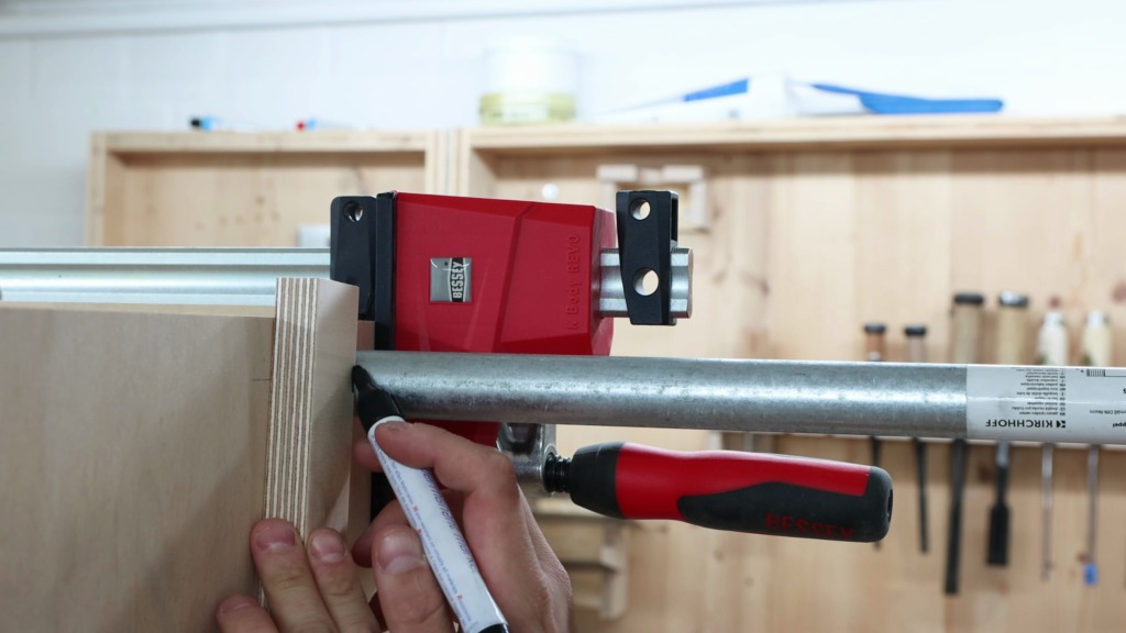
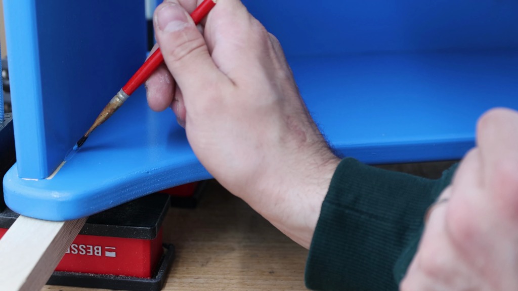
I glued the other french cleat strip to the back of the rack. Held it in place temporarily with a clamp and again secured it with screws.
At the bottom of the rack I attach a regular strip of ply to the back to accomodate for the distance to the wall the french cleat creates. After lifting the rack on the wall I drilled throuh the back panel and the wood strip to get marks on the wall for the wall anchors.


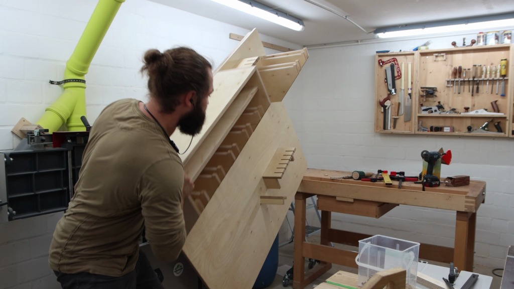


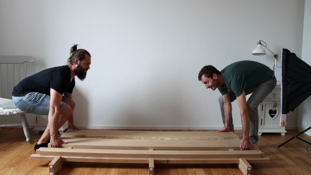
You might have wondered how I got the rack on the wall. Well that’s how. Let me first tell you that sucker is heavy. I leaned it on one corner in order for the other corner to get on my bench. Then I pushed it on my bench. Went around the bench, hoping it doesn’t fall over. With one foot on the bench and my elbow on my thigh, I could use my leg to lift most of the weight. Unconventional but it worked!
The last step of attaching it to the wall was to drive the screws through the bottom strip.


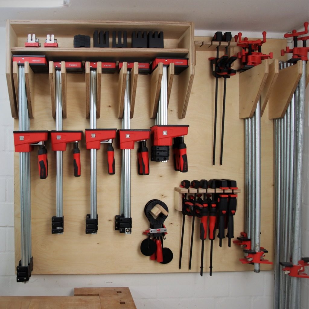

Finally, it was time for the best part of the build. Putting all the clamps in their new place. Parallel jaw clamps, Parallel jaw clamps, more Parallel jaw clamps, and one more Parallel jaw clamp. One-handed clamps, the band strap clamps and the pipe clamps.
And the accessories for the parallel jaw clamps