
I was running out of space in my small basement shop and still wanted fit in more tools. So a flip top tool stand should do the trick.
Tools I used
- Kreg K4 Master System
- Kreg Drawer Slide Jig
- Track Saw
- Table Saw
- Band saw
- Router
- Round over bit
- Random orbital sander
Materials and supplies
- 18mm (3/4″) birch plywood
- 12 mm (1/2″) plywood
- 3/4″ steel water pipe, length 1m (40″)
- Kreg Pocket holes screws kit
- 450mm (18″) drawer slides (4 sets)
- 250mm (10″) drawer slides (1 set)
- 125mm (5″) casters (4x)
- Spring-loaded indexing pins (4x)
- Scrap pieces of solid beech
- 5 drawer pulls
- 2 Outlets
- 2 distributor boxes
Breaking down the plywood
In our driveway, I started by breaking down 18mm birch plywood. My daughter was supervising the whole process and made sure I stick to the plan.
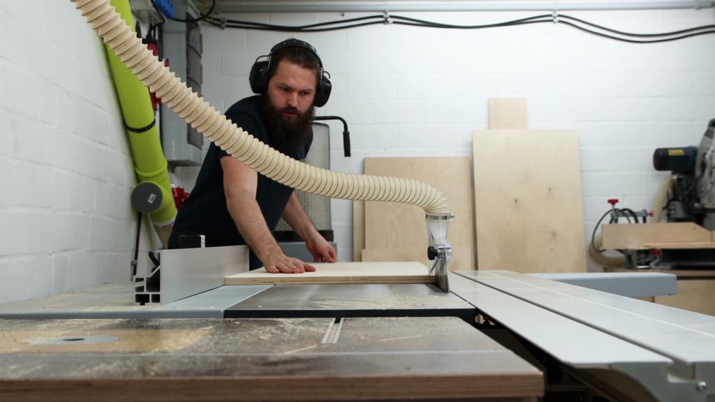
After a few cuts the plywood was handy enough to continue in the shop. I ripped a clean edge on each piece with Fritz and Franz and made a second rip cut to the final width with the rip fence. Then I could crosscut the pieces to length.

Pocket hole joinery for the cabinet
With my T-Square I marked the positions where the pocket holes would go. You can skip this step and just place them by eye, which works totally fine.
Speaking of pocket holes. Kreg, the sponsor of this build, hooked me up with their K4 master system. Let me tell you it was a totally different game then the cheap pocket hole jig from the hardware store, I’ve used prior to that.


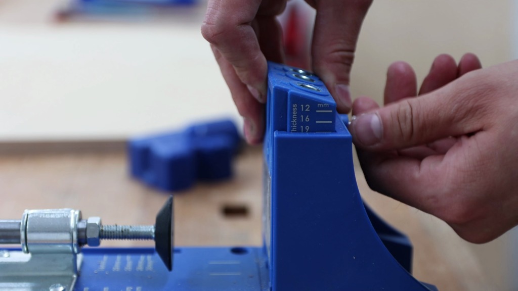


I secured the jig to two scrap pieces that form an L and could clamp it in my vise. For the adjustment of the depth stop of the drill bit, the jig offers this scale. Since I used 18mm material, I set the stop to the next larger setting of 19mm. The same applied for the drill guide in the jig itself. Then I inserted the dust collection attachment. Unfortunately, my dust port didn’t fit, but nothing a piece of duct tape couldn’t fix.
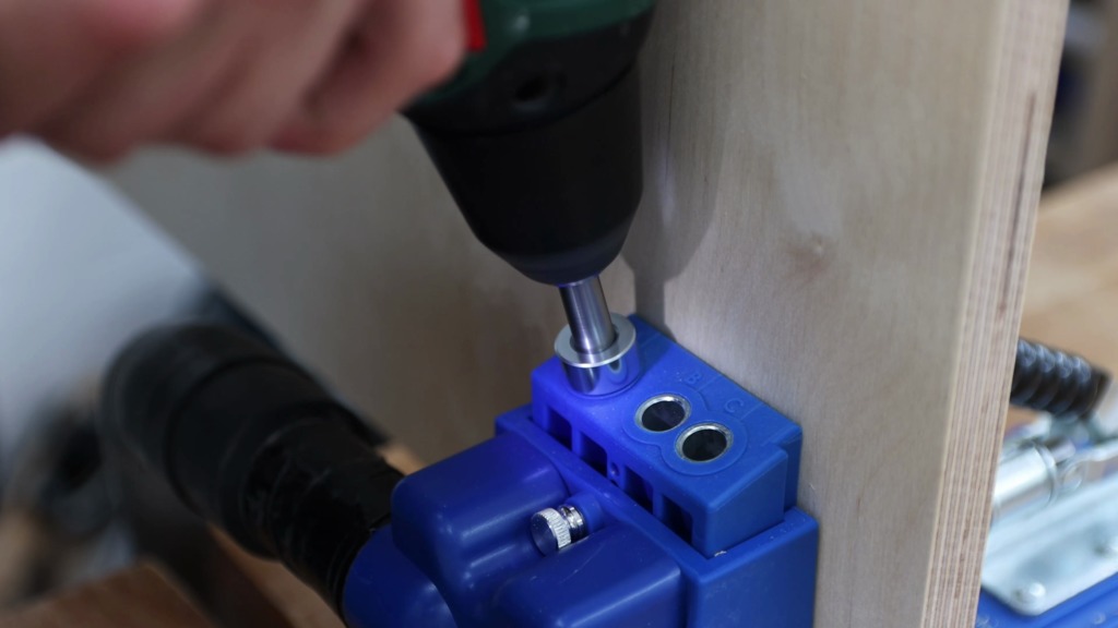
I aligned the marks of my boards with the marks on the jig and clamped it tight. Turned on the dust collection and here we go. I was really impressed by how well the dust collection worked on this jig. This doesn’t only save me the hassle of cleaning my shop, but also leads to cleaner pocket holes.
After I’ve applied some glue to the edges, I clamped the parts for the main cabinet together with the right angle clamp and added a bar clamp. With the 25mm coarse-threaded screws I screwed it in place.
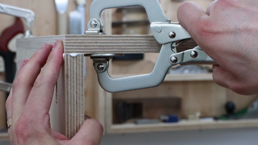

I did the same for the other side and made sure the parts stay flush by holding it in position with a face clamp.
As usual when I try to make something square, it wasn’t dead on and I forced it square.
Get the plans for this build
Get the plans with detail drawings and all measurements to build your own flip-top tool cart.

The Flip Top
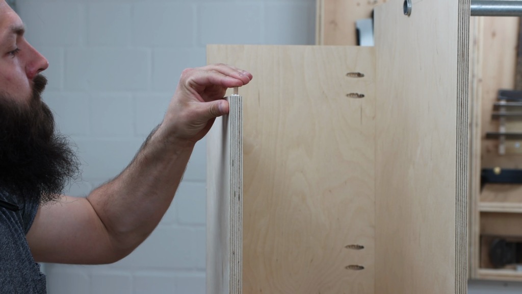
After the glue has dried I marked the location of the holes, where the bar for the flip-top will be. With a 27mm forstner bit, I drilled a hole half-way through. And because I found the slow-motion mode on my camera, you get this slow-mo shot of the chips flying away. In the center of the hole, I drilled all the way through with my smallest drill bit. Then I could finish the hole from the other side and end up with a tear-out free and perfect hole.


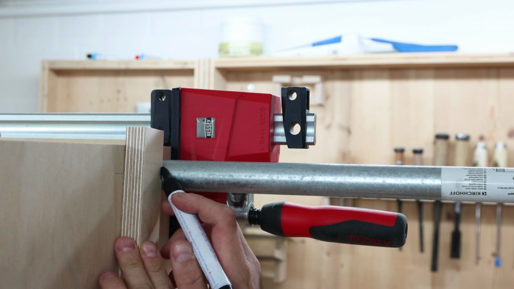


In order to make the flip-top flip, it rotates on a 3/4″ steel water pipe. I slipped it through the holes and gave it a little strength test with a couple of pull ups. Strong enough for me. To have the exact distance between the two sides, I used one of the boards that will be the top later on, as a spacer.
On one end I marked the pipe flush with the side panel and on the other side I added my material thickness of 18mm.
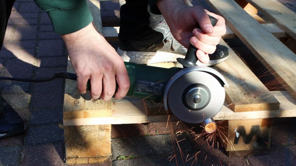
That day I was not in the mood of setting my shop on fire and went outside to cut the steel pipe. I used an angle grinder with a cutting disc for steel and really enjoyed seeing the sparks dance in the pipe.
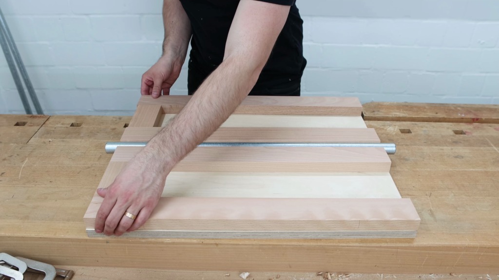
Back in the shop I eased the edges with a file. The flip-top is made of two plywood panels sandwiched together with the pipe in the middle. To compensate for the steel pipe I used some solid beech I had laying around from another project. I milled it to the exact thickness of the pipes outer diameter. I ripped the beech to 60mm strips and crosscut them to length.
Two long strips hold the pipe in the center and pieces along the edges make sure it becomes a sturdy top.
With wood glue and a couple of screws I attched the beech strips to the plywood. In order to ensure a tight and wiggle free fit I lightly clamped the pipe between the center strips before screwing the remaining pieces to the plywood.
Next I placed my sander on the top of it and marked the screw hole locations. I added a strip of wood at each location to give the screws a little more to bite on, when the sander will get installed. For the drill press I could use one of the strips in the center.
After spreading the glue I dropped the second plywood panel on top of it. I made sure it is flush and added a clamp or two more then necessary.
When I test-fitted the top I realized I made the hole for the pipe to high and therefore the top was not flush with the sides. To accommodate for it I milled two beech strips to size and glued them in place with a couple of pieces of tape to apply clamping pressure.
Building the side compartments
The cabinet has two side compartments. The right one has a front, a back and a bottom and is accessible from the side and top. The left one has 4 drawers to the front and one to the side. The top acts as another worksurface.
I marked the pocket hole locations on all the panels and drilled them with the same settings as before. To make assembly easier I used my bar clamps as a stop and screwed the compartment together.
I stroke a line where the bottom of the side compartment should be. This is crucial since the casters get screwed to the compartment and make the center portion of the cabinet hovering just 2 centimeters over the ground. You’ll see what I mean later on.
I screwed the compartment on the bottom and the sides to the cabinet.
For the left compartment I followed the same procedure. Because the cabinet was getting too high for my low ceilings I had to attach it upright. By positioning two face clamps to my line, I could stand the compartment on top of them and hold them with just another single clamp at the top. Again screws at the bottom and sides.
The top is a bit tricky, because of the drawers that open in two different directions. The the two side panels only overlap at a small square in front. To enforce this glue joint I used a 6mm wood dowel. With the combo square set to half of the material thickness I laid out the location for the dowel. I drilled a hole in both pieces with tape as a depth stop. Then I could apply glue and attach the top to the compartment.
The left compartment is inset 18mm (3/4″) to the front of the cabinet in order to accommodate for the drawer fronts and make them flush with the cabinet. On top, where the drawer opens to the side I needed a trim to make the top flush to the drawers as well. I glued it on the front and secured it with a few screws from the back.
Building sturdy pocket hole drawers
On to the step that gave me the most headache on this project. Breaking down a full sheet of 12mm ply in my shop for the drawers. It was raining outside and I couldn’t do it in the driveway. What you don’t see: I had to roll the bandsaw out of the shop, dissamble the fence of my jointer, roll it elsewhere in my shop and clean up all the junk that has piled up on my router table/outfeed table.
And still the dust hose blocking my way. Ducked tape for the rescue. Yes I was happy this step was done!
From there on the drawers where piece of cake.
Formatting sheet goods on a slider feels so productive and I enjoyed the following cuts were much.
Alright, all the parts for the drawers where cut and it was time for some more pocket holes.
I changed the settings to 12mm on the jig and drilled holes in the fronts and backs of the drawers.
The drawers will get a glued on front anyways and therefore the holes will be hidden.


For the assembly of the drawer boxes, the young lady from quality management (a.k.a. my daughter) was paying me a visit again. This time she assisted me by handpicking the screws.
I installed the drawer bottoms right away. By making sure the sides of the drawers are flush with the bottom, the drawers end up perfectly square. I drilled some holes, countersunk them and drove in the hand selected screws.
Sanding and finish
Plywood usually is pretty smooth. So I only gave it a very light 220 grid sanding.


With a chamfer bit in my trim router I tackled the edges and really like the look of the plywood facets.
As a finish I used Osmo and in order to save some time I applied it with a paint roller. It worked great and the cabinet was finished pretty fast. The edges got an extra thick coat, since the endgrain in the plywood soaks up much more finish.
Drawer installation
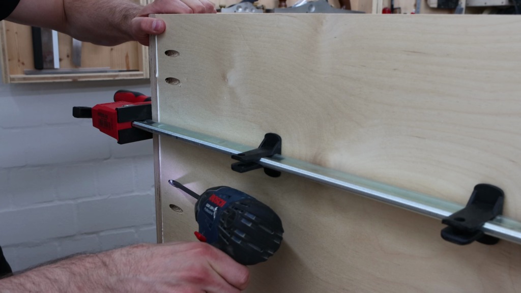
For drawer installation I started with the top drawer that opens to the side. To have a reference surface I clamped a scrap piece to the bottom of the side of the cabinet. Onto that I could place my drawer slide and because it is an inset drawer front, I placed the slide to the inside edge of the cabinet front.
After screwing the silde in place, I cut a spacer that fit between the top and the drawer slide as a reference for the other side.


The face clamp provided great help to hold the spacer in place and installing the second slide went smooth.
To attach the drawer box, I clamped the Kreg drawer slide jigs to the cabinet and placed the drawer box on them. With the slides flush to the front of the box, I could screw them down.
I always have a deck of cards lying around in the shop for spacing parts equally. I fit as many cards as possible in the whole gap and then divide them up in to the number of gaps. In this case two: Left and right. The same applies for top and bottom.
I put some double sided tape on the drawer box fronts to hold the front temporarily and applied some glue.
Using the cards as spacers, I press the front onto the box.
Then I was able to open the drawer and secure the front with a clamp. A couple of screws from the back make sure this front is going nowhere.
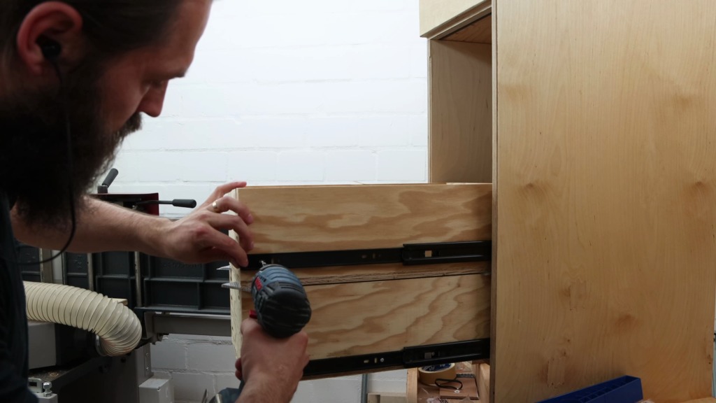
For the drawers that open to the other side, I registered the lower pair of slide on the bottom of the cabinet. Since these drawers have overlaying fronts on the left and inset drawers on the right, I made the slides flush with the cabinet on the left and inset on the right.
After installing the bottom drawer box I used a scrap piece to position the next set of drawer slides. With the bottom drawer and the slides fully extended I applied the card trick to attach the second drawer box.
I worked my way the top with this method.
Now was a good time to add some temporary drawer pulls out of tape.
Attaching the drawer fronts was very similar to the other drawer I had already installed. Double sided tape, glue, a clamp and a few screws from the back did the trick.
The cards made sure the gaps were even once again. and they did their job pretty well.
Attaching the casters and getting it off the workbench
After marking center on the fronts, I attached some drawer pulls, I had on hand.

Then I attached the casters to the bottom of the side compartments and double-checked they could swivel around freely.
Getting the cabinet of my workbench was way harder than I’ve expected. Somehow I made it work but I was definitely not favourable for my back.
End caps for the flip top with holes for the cable management
By sliding the water pipe through the top I finally gave the tool cart its coolest feature.

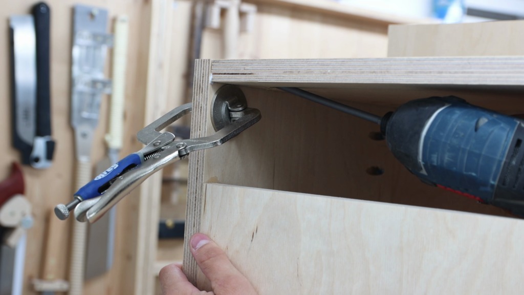
Remember that I made the pipe one material thickness longer than the cabinet is wide? This is for two end caps that give additional support for the pipe. I took 2 rectangular pieces of plywood and drilled a hole in the size of the pipe half way through. Then I switched to a smaller forstner bit and continued the hole. This is necessary for the power cord that will run in the pipe and a small chamfer will save the cord from wearing down.
Indexing pins to secure the flip top
The flip-top needed a way of locking it in its two positions. Therefore I got these spring loaded indexing pins. I marked their location and used a backer board when drilling the 12mm hole to avoid tear-out.
I traced the shape of the nut with my marking knife and chiseled the recess for it. The flip-top would otherwise interfere with the pertruding nut.
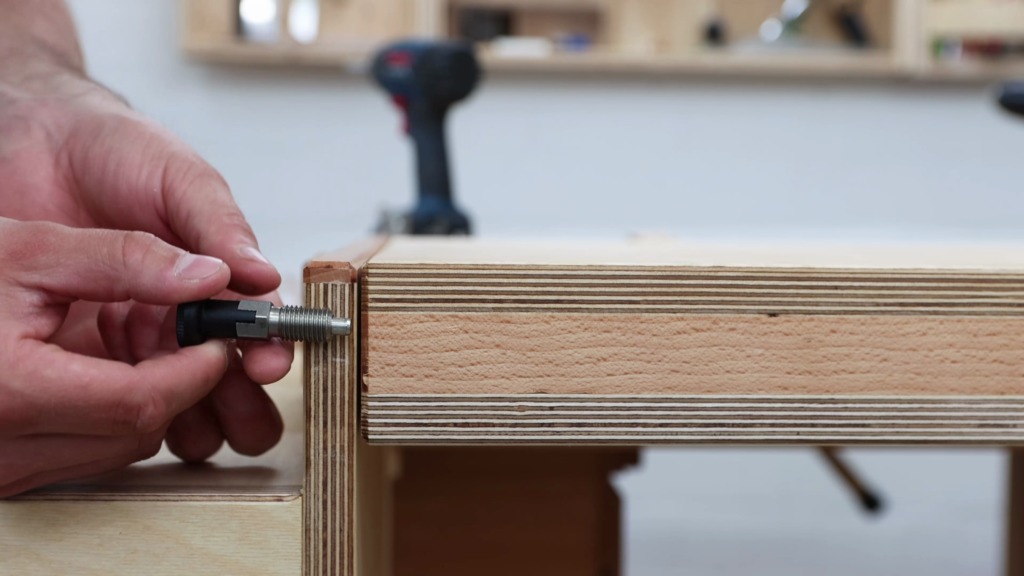


With a washer on the outside I fastened the indexing pin and it worked great. I used 4 indexing pin, one on each corner. But in hindsight I think the 2 in the front are enough and make the flipping operation even faster.
I wanted to be able to have both machines on the tool stand plugged in all the time and don’t worry about the stupid cords. Therefore I decided to run a main cord through the center of the pipe and hook it up to both sides of the flip-top.

Outlets on both sides of the flip top
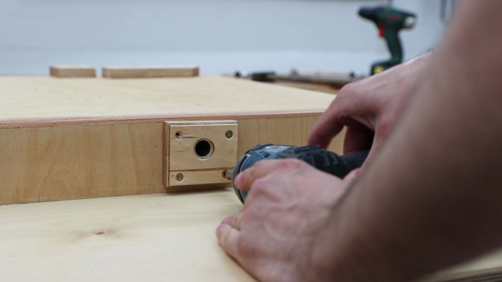
With the cord in the pipe I hooked it up to a small distributor box that connects to an additional outlet and the extension cord that gets plugged into the wall.
Each side of the flip top received an outlet that are connected with another cord that goes through the top.

Important to note with my setup is that the top cannot turn endlessly in the same direction because the cord in the pipe would spiral up and break eventually. I can only flip back and forth.
Finally it could place the machines. I pre-drilled the holes for the fasteners and tightened them. If you are wondering why I am using these rusty bolts, it’s because these are the very same bolts my granddad used to attach this drill press to his workbench years ago.
Holders for accessories
The belts for my belt sander tend to take way to much space, so a holder for these was way overdue. A piece of scrap cut a bit longer than the belts are wide makes a great storing solution. To prevent the belts from sliding off created a hook at the bandsaw.
Some magic to make the holder look a bit nicer, two pocket screws and I don’t have to worry about these guys anymore.


For the cast iron table of my sander, I needed a holder as well. Therefore I sandwiched a bunch of scraps together to receive the thorn of the table and drilled pocket holes to be able to attach it to the cabinet. No fancy joinery here with just glue and screws. Now the table has a nice place to go to.
The top could still rotate freely around the pipe and I realized this could break the cables inside. I drilled a pilot hole through the top and into the pipe. A beefy screw connects the top and the pipe.
Third worksurface for the Kreg K4 Master System.
I designed the cart in a way to have a third worksurface on which my pocket hole jig has a permanent spot. The drawer underneath is for all the accessoires: drill bits, bits, clamps and screws.
Of course I loaded up all the other drawers as well. Drill bits, more drill bits, special drill bits and more special drill bits.
More kreg accessories and accessories for my sander.
The flip top tool cart is done!


AAAAnd here it is. Looks a bit like a low rider and I like it! The integrated cable management is so convenient, since you only have to plug in that extension cord. The flipping feature works beautifully and the spring loaded indexing pins make it enjoyable. The third worksurface with its dedicated drawers is now always ready for some pocket holes and the other drawers provide plenty of storage.
Get the plans for this build
Get the plans with detail drawings and all measurements to build your own flip-top tool cart.